


PPC-51xxA-H61 Panel PC
Page ix
List of Figures
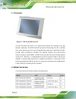
Figure 1-1: PPC-51xxA-H61 Panel PC...........................................................................................2
Figure 1-2: Front View ....................................................................................................................4
Figure 1-3: Rear View .....................................................................................................................5
Figure 1-4: Top View.......................................................................................................................5
Figure 1-5: PPC-5150A-H61/PPC-5170A-H61 Bottom View ........................................................7
Figure 1-6: PPC-5190A-H61 Bottom View ....................................................................................8
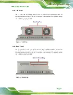
Figure 1-7: Left View.......................................................................................................................9
Figure 1-8: Right View ....................................................................................................................9
Figure 1-9: Internal Components ................................................................................................10
Figure 1-10: PPC-5150A-H61 Dimensions (mm)........................................................................11
Figure 1-11: PPC-5170A-H61 Dimensions (mm)........................................................................12
Figure 1-12: PPC-5190A-H61 Dimensions (mm)........................................................................13
Figure 3-1: PPC-5150A-H61 Back Cover Retention Screws.....................................................25
Figure 3-2: COM1 to COM5 Pin 9 Setting Jumper Locations ...................................................28
Figure 3-3: COM5 RS-232/422/485 Serial Port Selection Jumper Location ............................29
Figure 3-4: HDD Bracket Retention Screws...............................................................................30
Figure 3-5: HDD Retention Screws .............................................................................................31
Figure 3-6: Replacing the HDD Bracket .....................................................................................31
Figure 3-7: CompactFlash® Cover Plate....................................................................................32
Figure 3-8: Installing the CompactFlash® Card ........................................................................32
Figure 3-9: Replacing the CompactFlash® Cover Plate ...........................................................33
Figure 3-10: Optical Drive Bracket Retention Screws ..............................................................34
Figure 3-11: Optical Drive Blank Plate Assembly .....................................................................34
Figure 3-12: Optical Drive Screws ..............................................................................................35
Figure 3-13: Optical Drive SATA Cable ......................................................................................35
Figure 3-14: Replacing the Optical Drive Bracket .....................................................................36
Figure 3-15: Installing the PCI Riser Card..................................................................................38
Figure 3-16: Expansion Slot Retention Screw ...........................................................................38
Figure 3-17: Installing the PCI Card............................................................................................39
Figure 3-18: Installing the PCIe Riser Card................................................................................41
Figure 3-19: Expansion Slot Retention Screw ...........................................................................41
Содержание PPC-51 A-H61 Series
Страница 11: ...PPC 51xxA H61 Panel PC Page xi Figure 6 2 Main Board Layout Diagram Solder Side 106 ...
Страница 14: ...PPC 51xxA H61 Panel PC Page 1 1 Introduction Chapter 1 ...
Страница 20: ...PPC 51xxA H61 Panel PC Page 7 Figure 1 5 PPC 5150A H61 PPC 5170A H61 Bottom View ...
Страница 25: ...PPC 51xxA H61 Panel PC Page 12 1 6 2 PPC 5170A H61 Dimensions Figure 1 11 PPC 5170A H61 Dimensions mm ...
Страница 26: ...PPC 51xxA H61 Panel PC Page 13 1 6 3 PPC 5190A H61 Dimensions Figure 1 12 PPC 5190A H61 Dimensions mm ...
Страница 30: ...PPC 51xxA H61 Panel PC Page 17 2 Unpacking Chapter 2 ...
Страница 35: ...PPC 51xxA H61 Panel PC Page 22 3 Installation Chapter 3 ...
Страница 49: ...PPC 51xxA H61 Panel PC Page 36 Figure 3 14 Replacing the Optical Drive Bracket ...
Страница 75: ...PPC 51xxA H61 Panel PC Page 62 Chapter 4 4 System Maintenance ...
Страница 84: ...PPC 51xxA H61 Panel PC Page 71 5 BIOS Setup Chapter 5 ...
Страница 117: ...PPC 51xxA H61 Panel PC Page 104 6 Interface Connectors Chapter 6 ...
Страница 136: ...PPC 51xxA H61 Panel PC Page 123 Appendix A A Regulatory Compliance ...
Страница 141: ...PPC 51xxA H61 Panel PC Page 128 B BIOS Configuration Options Appendix B ...
Страница 144: ...PPC 51xxA H61 Panel PC Page 131 C Safety Precautions Appendix C ...
Страница 149: ...PPC 51xxA H61 Panel PC Page 136 D Watchdog Timer Appendix D ...
Страница 152: ...PPC 51xxA H61 Panel PC Page 139 E Hazardous Materials Disclosure Appendix E ...


