PPC-51xxA-H61 Panel PC
Page
x
Figure 3-20: Installing the PCIe Card..........................................................................................42
Figure 3-21: AT/ATX Mode Selection..........................................................................................42
Figure 3-22: Wall-mounting Bracket ...........................................................................................44
Figure 3-23: Mount the Chassis ..................................................................................................45
Figure 3-24: Secure the Chassis .................................................................................................46
Figure 3-25: PPC-5150A-H61 Panel Cutout Dimensions ..........................................................47
Figure 3-26: PPC-5170A-H61 Panel Cutout Dimensions ..........................................................47
Figure 3-27: PPC-5190A-H61 Panel Cutout Dimensions ..........................................................47
Figure 3-28: Panel Mounting Clamp Positions ..........................................................................48
Figure 3-29: Tighten the Panel Mounting Clamp Screws .........................................................49
Figure 3-30: Arm Mounting Retention Screw Holes..................................................................50
Figure 3-31: Stand Mounting Retention Screw Holes...............................................................51
Figure 3-32: SFP Fiber Module Installation................................................................................52
Figure 3-33: RJ-45 LAN Connector .............................................................................................53
Figure 3-34: LAN Connection ......................................................................................................54
Figure 3-35: RS-232 Serial Port ...................................................................................................54
Figure 3-36: RS-232 Serial Device Connector ...........................................................................55
Figure 3-37: RS-232/422/485 Serial Port .....................................................................................56
Figure 3-38: RS-232/422/485 Serial Device Connector .............................................................57
Figure 3-39: USB Device Connection .........................................................................................58
Figure 3-40: VGA Connector .......................................................................................................59
Figure 3-41: VGA Connector .......................................................................................................60
Figure 3-42: Driver Menu .............................................................................................................61
Figure 4-1: SO-DIMM Module Locations.....................................................................................64
Figure 4-2: SO-DIMM Module Installation...................................................................................65
Figure 4-3: PPC-5150A-H61 Top Panel Elevated Platform Screws..........................................65
Figure 4-4: PPC-5150A-H61Side Panel Elevated Platform Screws..........................................66
Figure 4-5: PPC-5150A-H61Bottom Panel Elevated Platform Screws.....................................66
Figure 4-6: PPC-5150A-H61Internal Elevated Platform Screws...............................................66
Figure 4-7: PSU Power Cables ....................................................................................................67
Figure 4-8: PSU Bottom Panel Retention Screws .....................................................................68
Figure 4-9: PSU Bottom Panel Screws .......................................................................................68
Figure 4-10: System Cooling Fans Motherboard Connector ...................................................69
Figure 4-11: System Cooling Fans Left Panel Retention Screws............................................70
Figure 6-1: Main Board Layout Diagram (Front Side) ............................................................ 105
Содержание PPC-51 A-H61 Series
Страница 11: ...PPC 51xxA H61 Panel PC Page xi Figure 6 2 Main Board Layout Diagram Solder Side 106 ...
Страница 14: ...PPC 51xxA H61 Panel PC Page 1 1 Introduction Chapter 1 ...
Страница 20: ...PPC 51xxA H61 Panel PC Page 7 Figure 1 5 PPC 5150A H61 PPC 5170A H61 Bottom View ...
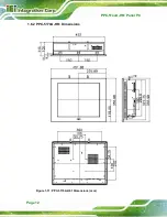
Страница 25: ...PPC 51xxA H61 Panel PC Page 12 1 6 2 PPC 5170A H61 Dimensions Figure 1 11 PPC 5170A H61 Dimensions mm ...
Страница 26: ...PPC 51xxA H61 Panel PC Page 13 1 6 3 PPC 5190A H61 Dimensions Figure 1 12 PPC 5190A H61 Dimensions mm ...
Страница 30: ...PPC 51xxA H61 Panel PC Page 17 2 Unpacking Chapter 2 ...
Страница 35: ...PPC 51xxA H61 Panel PC Page 22 3 Installation Chapter 3 ...
Страница 49: ...PPC 51xxA H61 Panel PC Page 36 Figure 3 14 Replacing the Optical Drive Bracket ...
Страница 75: ...PPC 51xxA H61 Panel PC Page 62 Chapter 4 4 System Maintenance ...
Страница 84: ...PPC 51xxA H61 Panel PC Page 71 5 BIOS Setup Chapter 5 ...
Страница 117: ...PPC 51xxA H61 Panel PC Page 104 6 Interface Connectors Chapter 6 ...
Страница 136: ...PPC 51xxA H61 Panel PC Page 123 Appendix A A Regulatory Compliance ...
Страница 141: ...PPC 51xxA H61 Panel PC Page 128 B BIOS Configuration Options Appendix B ...
Страница 144: ...PPC 51xxA H61 Panel PC Page 131 C Safety Precautions Appendix C ...
Страница 149: ...PPC 51xxA H61 Panel PC Page 136 D Watchdog Timer Appendix D ...
Страница 152: ...PPC 51xxA H61 Panel PC Page 139 E Hazardous Materials Disclosure Appendix E ...

