background image


EP-265-GM45/EP-267-GM45 Enrich POS System


Page 53 

5.1 System Maintenance Introduction 

If the components of the EP-265-GM45/EP-267-GM45 series fail they must be replaced. 

Components that can be replaced include: 


CF module 


SATA HDD 


Wireless LAN module 


DIMM module 

Please contact the system reseller or vendor to purchase the replacement parts. Back 

cover removal instructions and component replacement for the 

EP-265-GM45/EP-267-GM45 series are described below. 

5.2 Anti-static Precautions 

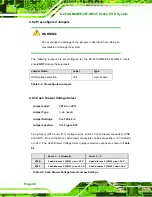
 WARNING: 

Failure to take ESD precautions during the maintenance of the 

EP-265-GM45/EP-267-GM45 may result in permanent damage to the 

EP-265-GM45/EP-267-GM45 and severe injury to the user.   

Electrostatic discharge (ESD) can cause serious damage to electronic components, 

including the EP series. Dry climates are especially susceptible to ESD. It is therefore 

critical that whenever the EP series is accessed internally, or any other electrical 

component is handled, the following anti-static precautions are strictly adhered to. 


Wear an anti-static wristband

: - Wearing a simple anti-static wristband can 

help to prevent ESD from damaging the board. 


Self-grounding

:- Before handling the board touch any grounded conducting 

material. During the time the board is handled, frequently touch any 

conducting materials that are connected to the ground. 


Use an anti-static pad

: When configuring the EP series, place it on an 

antic-static pad. This reduces the possibility of ESD damaging the EP series. 

Содержание EP-265-GM45

Страница 1: ...e i EP 265 GM45 EP 267 GM45 Enrich POS System MODEL EP 265 GM45 EP 267 GM45 Fanless Intel Celeron M Enrich POS System with Touch Screen 1 GB DDR2 PoweredUSB VGA 5 V 12 V Serial Ports and AT ATX Power...

Страница 2: ...E 265 GM45 EP 267 GM45 Enrich POS System Page ii Revision Date Version Changes 19 February 2009 1 00 Initial release...

Страница 3: ...al damages arising out of the use or inability to use the product or documentation even if advised of the possibility of such damages This document contains proprietary information protected by copyri...

Страница 4: ...the EP series from or contact an IEI sales representative directly To contact an IEI sales representative please send an email to sales iei com tw The items listed below should all be included in the...

Страница 5: ...l 8 1 3 SPECIFICATIONS 8 1 3 1 Preinstalled Hardware Components 8 1 3 2 System Specifications 9 2 DETAILED SPECIFICATIONS 12 2 1 DIMENSIONS 13 2 1 1 EP 265 GM45 Dimensions 13 2 1 2 EP 267 GM45 Dimensi...

Страница 6: ...23 2 8 1 1 AT Power Mode 23 2 8 1 2 ATX Power Mode 23 2 8 2 Power Supply 24 2 8 3 Power Connectors 24 2 8 3 1 Power Input Connector 25 2 8 3 2 Power Output Connector 25 2 8 4 RJ 12 Connectors for Cas...

Страница 7: ...10 4 USB Device Connection 49 4 10 5 Parallel Device Connection 50 5 SYSTEM MAINTENANCE 52 5 1 SYSTEM MAINTENANCE INTRODUCTION 53 5 2 ANTI STATIC PRECAUTIONS 53 5 3 TURN OFF THE POWER 54 5 4 REPLACING...

Страница 8: ...6 7 CHIPSET 94 6 7 1 North Bridge Chipset Configuration 95 6 7 2 SouthBridge Configuration 97 6 8 EXIT 99 7 SYSTEM MONITORING 101 7 1 IEI INTELLIGENT SYSTEM MANAGEMENT MODULE ISMM 102 7 1 1 What is i...

Страница 9: ...atic Precautions 115 C 2 MAINTENANCE AND CLEANING PRECAUTIONS 115 C 2 1 Maintenance and Cleaning 115 C 2 2 Cleaning Tools 116 D BIOS CONFIGURATION OPTIONS 117 D 1 BIOS CONFIGURATION OPTIONS 118 E WATC...

Страница 10: ...67 GM45 Dimensions mm 14 Figure 2 3 CPU and Chipsets Heat Sink 15 Figure 2 4 Memory Module and Memory Socket 16 Figure 2 5 SATA Hard Disk Drive Bays 16 Figure 2 6 CompactFlash Slot 17 Figure 2 7 COM P...

Страница 11: ...Voltage Select Jumper Location 42 Figure 4 12 Clear CMOS Jumper 43 Figure 4 13 COM3 COM4 and COM5 Pin 9 Setting Jumper Locations 44 Figure 4 14 I O Interface Cover Removal 45 Figure 4 15 Mounting Hole...

Страница 12: ...cifications 11 Table 4 1 Jumpers 38 Table 4 2 Preconfigured Jumpers 40 Table 4 3 Cash Drawer Voltage Select Jumper Settings 40 Table 4 4 CF Voltage Select Jumper Settings 41 Table 4 5 Clear CMOS Jumpe...

Страница 13: ...EP 265 GM45 EP 267 GM45 Enrich POS System Page 1 1 Introduction Chapter 1...

Страница 14: ...r hub GMCH coupled with an Intel ICH9M input output controller hub ensures optimal memory graphics and peripheral I O support The system comes with 1 0 GB of preinstalled DDR2 SDRAM and supports a max...

Страница 15: ...2 0 ports Two 12 V PoweredUSB ports and one 24 V PoweredUSB port Watchdog timer that triggers a system reset if the system hangs for some reasons iSMM system health supervision API to track the syste...

Страница 16: ...s inside the monitor rear panel The aluminum chassis consists of rear panel bottom panel and two side panels left and right The I O interface panel located on the rear panel of the EP 265 GM45 EP 267...

Страница 17: ...side panel of the EP 265 GM45 EP 267 GM45 monitor has a set of buttons to control the LCD brightness and the volume of the speakers The monitor right side panel also provides access to the I O interfa...

Страница 18: ...M port power selecting switch 12 V 5V The external I O interface connectors on the rear side of the monitor are shown in Figure 1 5 Figure 1 5 I O Interface Connectors on the Monitor Right Side Panel...

Страница 19: ...x Keyboard connector 1 x Mouse connector 1 x LAN connector 2 x USB 2 0 connectors 1 x Parallel port connector 2 x RJ 12 connectors 3 x 5 V 12 V serial port connectors COM3 COM4 and COM5 1 x VGA conne...

Страница 20: ...r on off Figure 1 7 Figure 1 7 EP 265 GM45 EP 267 GM45 Left Side View 1 3 Specifications 1 3 1 Preinstalled Hardware Components The EP 265 GM45 EP 267 GM45 POS system has the following preinstalled co...

Страница 21: ...4 x 768 XGA 1280 x 1024 SXGA Brightness 350 cd m2 300 cd m2 Contrast Ratio 400 1 800 1 LCD Color 262K 16 7M Pixel Pitch mm 0 297 H x 0 297 V 0 264 H x 0 264 V Viewing Angle H V 120 H 100 V 160 H 160 V...

Страница 22: ...8 30 kg 9 80 kg IP level front panel IP 64 EMC CE EMC and FCC Safety UL and CB Touch Screen Resistive Type 5 wire touch controller IC is on board 252 W Input 90 VAC 264 VAC 50 Hz 60 Hz Power Adapter...

Страница 23: ...RJ 12 connectors 3 x 5 V 12 V serial port connectors COM3 COM4 and COM5 1 x VGA connector 1 x Serial port connector COM1 1 x 12 V PoweredUSB connector 2 x USB 2 0 connectors I O Ports and Switches Mo...

Страница 24: ...E 265 GM45 EP 267 GM45 Enrich POS System Page 12 2 Detailed Specifications Chapter 2...

Страница 25: ...ns provide detailed schematics and information on the dimensions of the EP 265 GM45 EP 267 GM45 2 1 1 EP 265 GM45 Dimensions The dimensions of the EP 265 GM45 are shown in Figure 2 1 and listed below...

Страница 26: ...ight 414 52 mm Depth 350 47 mm Figure 2 2 EP 267 GM45 Dimensions mm 2 2 Intel Celeron M Processor Support A 2 0 GHz Intel Celeron M processor is installed in the system The processor has a CPU speed o...

Страница 27: ...nents The following sections describe some of the features on the motherboard 2 3 1 Memory Support 2 3 1 1 Installed Memory One 240 pin 1 0 GB DDR2 SDRAM DIMM is installed in the EP 265 GM45 EP 267 GM...

Страница 28: ...rage Capacity The EP 265 GM45 EP 267 GM45 comes with two hard disk drive bays for two 2 5 SATA HDDs Figure 2 5 The hard disk drive bay can be access by removing the bottom panels Figure 2 5 SATA Hard...

Страница 29: ...system 2 4 1 Serial Port Connectors The EP 265 GM45 EP 267 GM45 has four serial ports one on the monitor rear panel COM1 and three on the I O interface panel COM3 COM4 and COM5 Pin 9 on these four ser...

Страница 30: ...Southbridge The remaining four serial ports COM3 COM4 and COM5 are connected to the ICH9M LPC bus through a Fintek serial port controller 2 4 2 LAN Connectivity One of the PCI Express PCIe x1 lanes fr...

Страница 31: ...connectors two on the monitor rear panel and two on the chassis rear panel All of the USB 2 0 connectors are interfaced directly to the USB controllers on the ICH9M Southbridge The USB connectors are...

Страница 32: ...onnectors provide 12 V power to the peripheral devices The remaining one PoweredUSB provides 24 V power for higher power devices Figure 2 10 PoweredUSB Ports 2 4 4 Keyboard and Mouse Connectivity Two...

Страница 33: ...e touch screen is connected to the motherboard through the RS 232 interface COM 2 The sensitive touch screen is accurate reliable and durable A capacitive touch screen can be integrated into the EP se...

Страница 34: ...above The supported device include iSignager LCD series AFOLUX monitors Vacuum fluorescent display VFD 2 7 Audio 2 7 1 High Definition Audio Controller The Integrated audio controller on the Intel ICH...

Страница 35: ...witch The EP 265 GM45 EP 267 GM45 POS system turns on automatically when the power is connected The AT mode benefits a big retail store to control multiple POS systems from a central management center...

Страница 36: ...utput connectors The power supply is also equipped with two cooling fans The power supply is shown in below Figure 2 15 Power Supply Unit 2 8 3 Power Connectors There are two power connectors on the E...

Страница 37: ...s for Cash Drawer Power Two RJ 12 connectors on the chassis rear panel interface can provide 24 V or 12 V of power to a cash drawer The cash drawer control can be controlled through the digital I O an...

Страница 38: ...temperature within the system may result in irreparable damage to the POS system The EP 265 GM45 EP 267 GM45 POS System is an effective heat dissipation system The heat sink on the main board works to...

Страница 39: ...EP 265 GM45 EP 267 GM45 Enrich POS System Page 27 3 Unpacking Chapter 3...

Страница 40: ...d during the installation process Step 1 Use box cutters a knife or a sharp pair of scissors that seals the top side of the external second box Step 2 Open the external second box Step 3 Use box cutte...

Страница 41: ...POS system is shipped with the following components Quantity Item Image 1 EP 265 GM45 EP 267 GM45 POS system 1 Screw set 1 Power supply 1 Power cord 1 Touch pen 1 User manual CD and driver CD If any o...

Страница 42: ...E 265 GM45 EP 267 GM45 Enrich POS System Page 30 4 Installation Chapter 4...

Страница 43: ...d can help to prevent ESD from damaging the board Self grounding Before handling the board touch any grounded conducting material During the time the board is handled frequently touch any conducting m...

Страница 44: ...esistive type touch screen Wireless LAN module AT ATX power switch 3 W stereo speakers Preinstalled OEM customizations may include the following Different DDR2 memory module Hard disk drive CF card Co...

Страница 45: ...e bottom panels please follow the steps below Step 1 Adjust the monitor Figure 4 1 and turn the EP 265 GM45 EP 267 GM45 over to put the monitor front panel on the table Figure 4 1 Monitor Adjustment S...

Страница 46: ...on The EP series has one CF Type II slot To install the CF card follow the instructions below Step 1 Remove the bottom panels Refer to Section 4 5 Step 2 Install the CF Card Locate the CF card socket...

Страница 47: ...DD Installation The EP series has two HDD slots inside the bottom panel for two 2 5 SATA HDDs To install the HDD follow the instructions below Step 1 Remove the bottom panels Refer to Section 4 5 Step...

Страница 48: ...n the four retention screw holes on the both side of the HDD with the retention screw holes of the HDD bracket Insert four retention screws into the both sides of the HDD bracket to secure the HDD to...

Страница 49: ...a metal bridge used to close an electrical circuit It consists of two or three metal pins and a small metal clip often protected by a plastic cover that slides over the pins to connect them To CLOSE...

Страница 50: ...OS CLR_CMOS1 3 pin header COM3 Pin 9 setting JP7 3 pin header COM4 Pin 9 setting JP8 3 pin header COM5 Pin 9 setting JP9 3 pin header Table 4 1 Jumpers 4 8 1 Access the Jumpers To access the jumpers p...

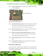
Страница 51: ...Screws Step 3 Remove the aluminum chassis The motherboard is installed inside the aluminum chassis To access the motherboard remove the four retention screws and gently lift the aluminum chassis off...

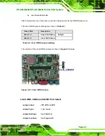
Страница 52: ...3 Cash Drawer Voltage Select Jumper Label JP10 and JP11 Jumper Type 3 pin header Jumper Settings See Table 4 3 Jumper Location See Figure 4 10 Two jumpers JP10 and JP11 configure pin 4 on RJ 12 cash...

Страница 53: ...4 8 4 CF Voltage Select Jumper Label JP6 Jumper Type 3 pin header Jumper Settings See Table 4 4 Jumper Location See Figure 4 11 The CF Voltage Select jumper sets the CF Type II slot can be set as eith...

Страница 54: ...e 4 12 If the EP 265 GM45 EP 267 GM45 fails to boot due to improper BIOS settings the clear CMOS jumper clears the CMOS data and resets the system BIOS information To do this use the jumper cap to clo...

Страница 55: ...hown in Table 4 5 Clear CMOS Description Short 1 2 Keep CMOS Setup Default Short 2 3 Clear CMOS Setup Table 4 5 Clear CMOS Jumper Settings The location of the clear CMOS jumper is shown in Figure 4 12...

Страница 56: ...se 5 V COM3 Pin 9 use 12 V JP8 COM4 Pin 9 use 5 V COM4 Pin 9 use 12 V JP9 COM5 Pin 9 use 5 V COM5 Pin 9 use 12 V Table 4 6 COM2 COM3 and COM5 Pin 9 Setting Jumper Settings The COM3 COM4 and COM5 Pin 9...

Страница 57: ...chassis from the rear of the EP 265 GM45 EP 267 GM45 Figure 4 15 Figure 4 15 Mounting Hole Cover Removal Step 3 Align the thee retention screw holes on the second display device with the retention scr...

Страница 58: ...ure 4 16 Second Display Installation Step 4 Organize the second display cables and connect the connector to the connectors on the I O interface panel Figure 4 17 Figure 4 17 Organized Second Display C...

Страница 59: ...ure 4 18 AT ATX Switch Step 2 Adjust the AT ATX switch The default mode is ATX mode Figure 4 18 Step 0 4 10 2 LAN Connection There is one external RJ 45 LAN connector The RJ 45 connector enables conne...

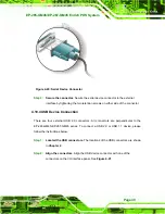
Страница 60: ...on The EP 265 GM45 EP 267 GM45 series has four male DB 9 connectors for serial devices to be connected Follow the steps below to connect a serial device to the EP 265 GM45 EP 267 GM45 series POS syste...

Страница 61: ...tep 0 4 10 4 USB Device Connection There are four external USB 2 0 connectors All connectors are perpendicular to the EP 265 GM45 EP 267 GM45 series To connect a USB 2 0 or USB 1 1 device please follo...

Страница 62: ...EP 265 GM45 EP 267 GM45 has a single female DB 25 connector on the chassis rear panel for parallel devices Follow the steps below to connect a parallel device to the EP 265 GM45 EP 267 GM45 Step 1 Loc...

Страница 63: ...Enrich POS System Page 51 Figure 4 22 Parallel Device Connector Step 3 Secure the connector Secure the DB 25 connector to the external interface by tightening the two retention screws on either side...

Страница 64: ...E 265 GM45 EP 267 GM45 Enrich POS System Page 52 5 System Maintenance Chapter 4...

Страница 65: ...EP 267 GM45 and severe injury to the user Electrostatic discharge ESD can cause serious damage to electronic components including the EP series Dry climates are especially susceptible to ESD It is the...

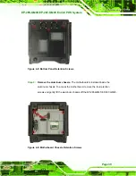
Страница 66: ...5 4 Replacing Components 5 4 1 Hard Disk Drive Replacement If the HDD fails please follow the steps below Step 1 Follow all anti static procedures See Section 5 2 Step 2 Turn off the power See Sectio...

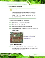
Страница 67: ...module please follow the steps below Step 1 Follow all anti static procedures See Section 5 2 Step 2 Turn off the power See Section 5 3 Step 3 Remove the internal aluminum chassis See Section 4 8 1 St...

Страница 68: ...dle of the DIMM must be aligned with the plastic bridge in the socket See Figure 5 2 Step 8 Insert the DIMM Once properly aligned the DIMM can be inserted into the socket As the DIMM is inserted the w...

Страница 69: ...the wireless module from the socket Step 7 Align the new wireless module with the Mini PCIe socket The wireless module must be oriented in such a way that the notch in the wireless module must be ali...

Страница 70: ...E 265 GM45 EP 267 GM45 Enrich POS System Page 58 6 AMI BIOS Setup Chapter 6...

Страница 71: ...SETUP message appears on the screen 0 If the message disappears before the DELETE key is pressed restart the computer and try again 6 1 2 Using Setup Use the arrow keys to highlight items press ENTER...

Страница 72: ...to Reboot After Configuration Changes If the computer cannot boot after changes to the system configuration is made CMOS defaults Use the jumper described in Chapter 5 6 1 5 BIOS Menu Bar The menu bar...

Страница 73: ...components The fields in System Overview cannot be changed The items shown in the system overview include AMI BIOS Displays auto detected BIOS information o Version Current BIOS version o Build Date...

Страница 74: ...he Advanced menu 5BIOS Menu 2 to configure the CPU and peripheral devices through the following sub menus WARNING Setting the wrong values in the sections below may cause the system to malfunction Mak...

Страница 75: ...P 267 GM45 Enrich POS System Page 63 BIOS Menu 2 Advanced 6 3 1 CPU Configuration Use the CPU Configuration menu 5BIOS Menu 3 to view detailed CPU specifications and configure the CPU BIOS Menu 3 CPU...

Страница 76: ...the FSB speed Cache L1 Lists the CPU L1 cache size Cache L2 Lists the CPU L2 cache size 6 3 2 IDE Configuration Use the IDE Configuration menu 5BIOS Menu 4 to change and or set the configuration of th...

Страница 77: ...ULT Configures SATA devices as normal IDE device AHCI Configures SATA devices as AHCI IDE Master and IDE Slave When entering setup BIOS auto detects the presence of IDE devices BIOS displays the statu...

Страница 78: ...eters The grayed out items in the left frame are IDE disk drive parameters automatically detected from the firmware of the selected IDE disk drive The drive parameters are listed as follows Device Lis...

Страница 79: ...l is supported 32Bit Data Transfer Enables 32 bit data transfer Type Auto Use the Type BIOS option select the type of device the AMIBIOS attempts to boot from after the Power On Self Test POST is comp...

Страница 80: ...o Use the Block Multi Sector Transfer to disable or enable BIOS to auto detect if the device supports multi sector transfers Disabled BIOS is prevented from using Multi Sector Transfer on the specifie...

Страница 81: ...rives manufactured after 1999 For other disk drives such as IDE CD ROM drives check the specifications of the drive DMA Mode Auto Use the DMA Mode BIOS selection to adjust the DMA mode options Auto DE...

Страница 82: ...Ultra DMA mode 4 selected with a maximum data transfer rate of 66 6MBps To use this mode it is required that an 80 conductor ATA cable is used UDMA5 Ultra DMA mode 5 selected with a maximum data tran...

Страница 83: ...Allows BIOS to use 32 bit data transfers on supported hard disk drives 6 3 3 Super IO Configuration Use the Super IO Configuration menu 5BIOS Menu 6 to set or change the configurations for the FDD co...

Страница 84: ...ss Disabled No base address is assigned to Serial Port 2 2F8 IRQ3 DEFAULT Serial Port 2 I O port address is 3F8 and the interrupt address is IRQ3 3E8 IRQ4 Serial Port 2 I O port address is 3E8 and the...

Страница 85: ...an the Normal mode ECP EPP The parallel port operates in the extended capabilities port ECP mode The ECP mode supports bi directional communication between the system and the parallel port device and...

Страница 86: ...Select RS232 or RS422 RS485 option to select the Serial Port 2 signaling mode RS232 DEFAULT Serial Port 2 signaling mode is RS 232 RS422 RS485 Serial Port 2 signaling mode is RS 422 RS 485 Serial Port...

Страница 87: ...3E8 Serial Port 5 I O port address is 3E8 2E8 Serial Port 5 I O port address is 2E8 2F0 DEFAULT Serial Port 5 I O port address is 2F0 2E0 Serial Port 5 I O port address is 2E0 3D8 Serial Port 5 I O p...

Страница 88: ...ardware Health Configuration FAN Mode Setting Full On Mode Use the CPU FAN Mode Setting option to configure the second fan Full On Mode DEFAULT Fan is on all the time Automatic mode Fan is off when th...

Страница 89: ...he fan to stop when the CPU is at a high temperature and therefore cause the system to be damaged The CPU Temp Limit of OFF option can only be set if the CPU FAN Mode Setting option is set to Automati...

Страница 90: ...on and enter a decimal number between 000 and 127 The temperature range is specified below Minimum Value 0 C Maximum Value 127 C CPU Fan Start PWM 070 The Fan 3 Start PWM option can only be set if the...

Страница 91: ...M The following system parameters and values are shown The system parameters that are monitored are System Temperatures The following system temperatures are monitored o CPU Temperature o System Tempe...

Страница 92: ...a master and hardware assisted native command queuing Use the AHCI Settings menu BIOS Menu 8 to report on the auto detection of devices connected to the onboard SATA drive connectors BIOS Menu 8 AHCI...

Страница 93: ...ation Menu SATA Port n Auto Use the SATA Port n option to enable the system to auto detect the type of drive connected to SATA drive connector n S M A R T Enabled Use the S M A R T option to enable S...

Страница 94: ...e access parameters The Remote Access Configuration is an AMIBIOS feature and allows a remote host running a terminal program to display and configure the BIOS settings BIOS Menu 10 Remote Access Conf...

Страница 95: ...ly accessed through COM2 COM3 System is remotely accessed through COM3 COM4 System is remotely accessed through COM4 COM5 System is remotely accessed through COM5 NOTE Make sure the selected COM port...

Страница 96: ...After BIOS POST option to specify when console redirection should occur Disabled The console is not redirected after POST Boot Loader Redirection is active during POST and during Boot Loader Always D...

Страница 97: ...onfiguration information and configure the USB settings BIOS Menu 11 USB Configuration USB Functions Enabled Use the USB Function option to enable or disable the USB controllers Disabled USB controlle...

Страница 98: ...hen this option is enabled any attached USB mouse or USB keyboard can control the system even when there is no USB driver loaded onto the system Disabled Legacy USB support disabled Enabled DEFAULT Le...

Страница 99: ...EP 267 GM45 Enrich POS System Page 87 6 3 8 Power Configuration The Power Configuration menu 5BIOS Menu 12 configures the Advanced Configuration and Power Interface ACPI options BIOS Menu 12 Power Co...

Страница 100: ...ngs WARNING Setting wrong values for the BIOS selections in the PCIPnP BIOS menu may cause the system to malfunction BIOS Menu 13 PCI PnP Configuration IRQ Available Use the IRQ address to specify wha...

Страница 101: ...11 IRQ 14 IRQ 15 DMA Channel Available Use the DMA Channel option to assign a specific DMA channel to a particular PCI PnP device Available DEFAULT The specified DMA is available to be used by PCI PnP...

Страница 102: ...nt of memory that should be reserved for legacy ISA devices Disabled DEFAULT No memory block reserved for legacy ISA devices 16K 16KB reserved for legacy ISA devices 32K 32KB reserved for legacy ISA d...

Страница 103: ...Boot Enabled Use the Quick Boot BIOS option to make the computer speed up the boot process Disabled No POST procedures are skipped Enabled DEFAULT Some POST procedures are skipped to decrease the syst...

Страница 104: ...oes not enable the keyboard Number Lock automatically To use the 10 keys on the keyboard press the Number Lock key located on the upper left hand corner of the 10 key pad The Number Lock LED on the ke...

Страница 105: ...upervisor Password to set or change a supervisor password The default for this option is Not Installed If a supervisor password must be installed select this field and enter the password After the pas...

Страница 106: ...all appears next to Change User Password 6 7 Chipset Use the Chipset menu 5BIOS Menu 17 to access the NorthBridge and SouthBridge configuration menus WARNING Setting the wrong values for the Chipset B...

Страница 107: ...Hole Disabled Use the Memory Hole option to reserve memory space between 15MB and 16MB for ISA expansion cards that require a specified area of memory to work properly If an older ISA expansion card i...

Страница 108: ...used by internal graphics device Enable 128MB 128MB of memory used by internal graphics device Boot Display Device Auto Use the Boot Display Device option to select the display device used by the syst...

Страница 109: ...roller option enables or disables the audio controller Enabled DEFAULT The on board High Definition audio controller is enabled Disabled The on board audio controller is disabled Spread Spectrum Mode...

Страница 110: ...ower Loss BIOS option to specify what state the system returns to if there is a sudden loss of power to the system Power Off The system remains turned off Power On The system turns on Last State DEFAU...

Страница 111: ...Exit Use the Save Changes and Exit option to save the changes made to the BIOS options and to exit the BIOS configuration setup program Discard Changes and Exit Use the Discard Changes and Exit option...

Страница 112: ...option to load the optimal default values for each of the parameters on the Setup menus F9 key can be used for this operation Load Failsafe Defaults Use the Load Failsafe Defaults option to load fails...

Страница 113: ...EP 265 GM45 EP 267 GM45 Enrich POS System Page 101 7 System Monitoring Chapter 7...

Страница 114: ...voltages cooling fan speeds watchdog timer and the digital I O setup status The iSMM quickly captures and reports system conditions to ensure operators can prevent system damage Figure 7 1 iSMM 7 1 2...

Страница 115: ...tion save and load 7 2 COM Port LED Indicators The four COM port connectors each have two LED indicators LED status indicators are described in below A red LED indicates the pin 9 signal on the COM po...

Страница 116: ...E 265 GM45 EP 267 GM45 Enrich POS System Page 104 A System Specifications Appendix A...

Страница 117: ...Hz or 800 MHz DDR2 SDRAM DIMM system max 2 0 GB System BIOS AMI BIOS Hard disk drives Two 3 0 Gb s SATA II VGA Integrated in the Intel GM45 LAN One GbE Expansion One PCIe Mini Super I O ITE IT8718F Au...

Страница 118: ...M170EG01 VD Resolution pixel XGA 1024 x 768 SXGA 1280 x 1024 Active Area mm 304 1 x 228 1 337 9 x 270 3 Pixel Pitch mm 0 297 0 264 Mode TN TN Number of Colors 262K 16 7M Color Saturation NTSC 65 72 Vi...

Страница 119: ...246 0 228 1 x 304 1 Total Transmission 78 78 Maximum Voltage DC 7V DC 7V Operating Temperature 10 C 50 C 10 C 40 C Operating Humidity 20 90 RH 20 90 RH Storage Temperature 20 C 70 C 20 C 70 C Storage...

Страница 120: ...at 3 3V Operating Voltage 3 3 V Dimensions 51 mm x 30 mm x 3 3 mm A 5 Power Supply Module A Sinpro power supply unit is provided with the system Specifications for the power supply unit are listed bel...

Страница 121: ...eter Minimum Typical Maximum Start up Time 0 3 1 5 2 Ripple and Noise peak to peak 0 5 1 Safety Ground Leakage Current mA 0 1 Temperature Coefficient C 0 04 0 04 Environmental Operating Temperature C...

Страница 122: ...E 265 GM45 EP 267 GM45 Enrich POS System Page 110 B External Connector Pinouts Appendix B...

Страница 123: ...h draw connectors PIN NO DESCRIPTION 1 Ground 2 Cash Drawer Open Control Signal 3 Cash Drawer Open Signal In 4 12 V 24 V jumper selection 5 N C 6 Ground RJ 12 Cash Drawer Pinouts B 3 Power Input Conne...

Страница 124: ...EP 265 GM45 EP 267 GM45 has a single 15 pin female connector for connectivity to standard display devices PIN DESCRIPTION PIN DESCRIPTION 1 RED 2 GREEN 3 BLUE 4 NC 5 GND 6 GND 7 GND 8 GND 9 VCC NC 10...

Страница 125: ...EP 265 GM45 EP 267 GM45 Enrich POS System Page 113 C Safety Precautions Appendix C...

Страница 126: ...is disconnected whenever the EP series is being installed moved or modified Do not apply voltage levels that exceed the specified voltage range Doing so may cause fire and or an electrical shock Elect...

Страница 127: ...e handling any electrical component touch any grounded conducting material During the time the electrical component is handled frequently touch any conducting materials that are connected to the groun...

Страница 128: ...ll be explicitly mentioned in the cleaning tips Below is a list of items to use when cleaning the EP series Cloth Although paper towels or tissues can be used a soft clean piece of cloth is recommende...

Страница 129: ...EP 265 GM45 EP 267 GM45 Enrich POS System Page 117 D BIOS Configuration Options Appendix D...

Страница 130: ...Parameters 66 Type Auto 67 ZIP 67 LS 120 68 LBA Large Mode Auto 68 Block Multi Sector Transfer Auto 68 PIO Mode Auto 68 DMA Mode Auto 69 S M A R T Auto 70 32Bit Data Transfer Enabled 71 Serial Port1 A...

Страница 131: ...after BIOS POST 83 Terminal Type 83 Serial Port Number COM1 83 Base Address IRQ 3F8h 4 83 Serial Port Mode 115200 8 n 1 83 Redirection After BIOS POST Always 84 Terminal Type ANSI 84 USB Functions En...

Страница 132: ...Enable 32MB 96 Boot Display Device Auto 96 Flat Panel Type BY HARDWARE 96 HDA Controller Enabled 97 Spread Spectrum Mode Disabled 97 Restore on AC Power Loss Last State 98 Cash drawer control Enabled...

Страница 133: ...EP 265 GM45 EP 267 GM45 Enrich POS System Page 121 E Watchdog Timer Appendix E...

Страница 134: ...state A BIOS function call INT 15H is used to control the Watchdog Timer INT 15H AH 6FH Sub function AL 2 Sets the Watchdog Timer s period BL Time out value Its unit second is dependent on the item Wa...

Страница 135: ...rwise the system resets Example program INITIAL TIMER PERIOD COUNTER W_LOOP MOV AX 6F02H setting the time out value MOV BX 05 time out value is 5 seconds INT 15H ADD THE APPLICATION PROGRAM HERE CMP E...

Страница 136: ...E 265 GM45 EP 267 GM45 Enrich POS System Page 124 F Hazardous Materials Disclosure Appendix F...

Страница 137: ...edges the presences of small quantities of certain materials in the product and is applicable to China RoHS only A label will be placed on each product to indicate the estimated Environmentally Friend...

Страница 138: ...ed Circuit Board X O O O O X Metal Fasteners X O O O O O Cable Assembly X O O O O X Fan Assembly X O O O O X Power Supply Assemblies X O O O O X Battery O O O O O O O This toxic or hazardous substance...

Страница 139: ...GM45 EP 267 GM45 Enrich POS System Page 127 RoHS RoHS Pb Hg Cd CR VI PBB PBDE X O O O O X X O O O O X X O O O O X X O O O O O X O O O O X X O O O O X X O O O O X O O O O O O O SJ T11363 2006 X SJ T113...

Отзывы: