ACT-08A-N270 Access Control Terminal
Page 55
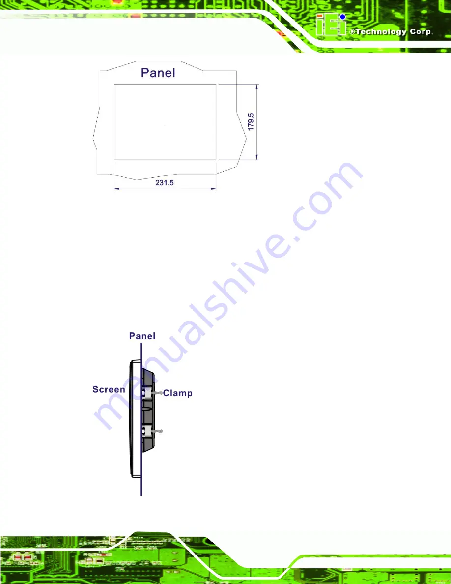
Figure 4-16: ACT-08A-N270 Panel Opening (mm)
Step 15:
Slide the flat panel PC through the hole until the frame is flush against the panel.
Step 16:
Insert the panel mounting clamps into the pre-formed holes along the edges of
the chassis, behind the frame.
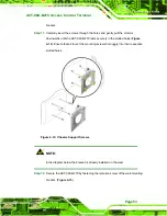
Step 17:
Tighten the screws that pass through the panel mounting clamps until the plastic
caps at the front of all the screws are firmly secured to the panel (
Step 17:
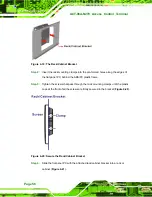
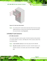
Figure 4-17: Tighten the Panel Mounting Clamp Screws
Содержание ACT-08A-N270
Страница 15: ...ACT 08A N270 Access Control Terminal Page 15 1 Introduction Chapter 1 ...
Страница 24: ...ACT 08A N270 Access Control Terminal Page 24 2 Detailed Specifications Chapter 2 ...
Страница 34: ...ACT 08A N270 Access Control Terminal Page 34 3 Unpacking Chapter 3 ...
Страница 37: ...ACT 08A N270 Access Control Terminal Page 37 4 Installation Chapter 4 ...
Страница 63: ...ACT 08A N270 Access Control Terminal Page 63 5 RFID Reader Chapter 5 ...
Страница 77: ...ACT 08A N270 Access Control Terminal Page 77 6 System Maintenance Chapter 6 ...
Страница 85: ...ACT 08A N270 Access Control Terminal Page 85 7 AMI BIOS Setup Chapter 7 ...
Страница 128: ...ACT 08A N270 Access Control Terminal Page 128 A System Specifications Appendix A ...
Страница 132: ...ACT 08A N270 Access Control Terminal Page 132 B External Connector Pinouts Appendix B ...
Страница 136: ...ACT 08A N270 Access Control Terminal Page 136 C Safety Precautions Appendix C ...
Страница 140: ...ACT 08A N270 Access Control Terminal Page 140 D BIOS Configuration Options Appendix D ...
Страница 144: ...ACT 08A N270 Access Control Terminal Page 144 E Watchdog Timer Appendix E ...
Страница 147: ...ACT 08A N270 Access Control Terminal Page 147 F Hazardous Materials Disclosure Appendix F ...

