ACT-08A-N270 Access Control Terminal
Page 40
4.5 Rear Panel Removal
WARNING:
Over-tightening rear panel screws will crack the plastic frame.
Maximum torque for cover screws is 5 kg-cm (0.36 lb-ft/0.49 Nm).
To access the CF slot and AT/ATX switch, the rear panel must be removed. To remove the
rear panel, please follow the steps below.
Step 1:
Put the front panel of the ACT-08A-N270 on a table.
Step 2:
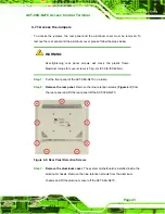
Remove the rear panel
. Remove the nine retention screws (
) from
the rear panel and lift the back cover off the ACT-08A-N270.
Step 0:
Figure 4-1: Rear Panel Retention Screws
4.6 CF Card Installation
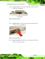
The ACT-08A-N270 has one CF Type II slot. To install the CF card, follow the instructions
below.
Step 1:
Remove the rear panel
. Refer to
Section 4.5
.
Содержание ACT-08A-N270
Страница 15: ...ACT 08A N270 Access Control Terminal Page 15 1 Introduction Chapter 1 ...
Страница 24: ...ACT 08A N270 Access Control Terminal Page 24 2 Detailed Specifications Chapter 2 ...
Страница 34: ...ACT 08A N270 Access Control Terminal Page 34 3 Unpacking Chapter 3 ...
Страница 37: ...ACT 08A N270 Access Control Terminal Page 37 4 Installation Chapter 4 ...
Страница 63: ...ACT 08A N270 Access Control Terminal Page 63 5 RFID Reader Chapter 5 ...
Страница 77: ...ACT 08A N270 Access Control Terminal Page 77 6 System Maintenance Chapter 6 ...
Страница 85: ...ACT 08A N270 Access Control Terminal Page 85 7 AMI BIOS Setup Chapter 7 ...
Страница 128: ...ACT 08A N270 Access Control Terminal Page 128 A System Specifications Appendix A ...
Страница 132: ...ACT 08A N270 Access Control Terminal Page 132 B External Connector Pinouts Appendix B ...
Страница 136: ...ACT 08A N270 Access Control Terminal Page 136 C Safety Precautions Appendix C ...
Страница 140: ...ACT 08A N270 Access Control Terminal Page 140 D BIOS Configuration Options Appendix D ...
Страница 144: ...ACT 08A N270 Access Control Terminal Page 144 E Watchdog Timer Appendix E ...
Страница 147: ...ACT 08A N270 Access Control Terminal Page 147 F Hazardous Materials Disclosure Appendix F ...

