PAGE
5
DOC: 374B
REV: 12-12
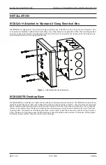
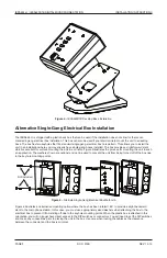
IEDA524-H / IEDA520DTB DIGITAL MICROPHONE STATION
INSTALLATION INSTRUCTIONS
9
11
10
12
+
–
S
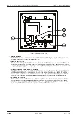
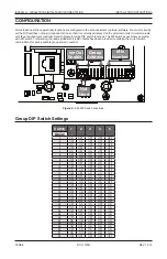
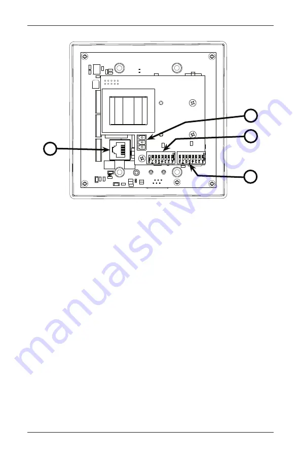
Figure 2 -
IEDA524-H Rear View
9. Ethernet Connector
Use this RJ45 connector to connect the device to a PoE network switch using Category 5e or better cable. The
PoE power consumption for the device is less than 2W.
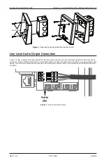
10. Line Level Audio Output
When the Line Level Output Enable DIP switch is on, the audio from the microphone will be routed to this output
connector when the network communications to the announcement controller is lost. This output can be wired to
a local amplifier to provide backup local paging in the event that the microphone station cannot communicate with
the announcement controller.
11. Group and Line Level Output Enable DIP Switches
DIP switches 1 through 5 are used to set the group number for this microphone station. This group number must
match the system number of the announcement controller that will own this microphone station. DIP switches 6
and 7 are not used. DIP switch 8 will enable the line level audio output when turned to the ON position. Refer to
“Group DIP Switch Settings” on page 9 for details on setting the proper group number on the DIP switches.
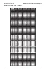
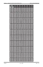
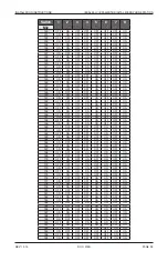
12. Mic Number DIP Switches
Use these DIP switches to set the mic number of this microphone station. This number is used to associate this
microphone station with the configuration in the announcement controller software. Each microphone station
owned by an announcement controller must have a unique mic number. Refer to “Mic Number DIP Switch Set-
tings” on page 10 for details on setting the proper mic number on the DIP switches.


