background image


 30 


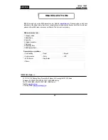
IDTECK accepts only on-line RMA requests on our Website (

www.idteck.com

). Please provide us with basic 

information in the below form so that we can understand your problems better. Send us back this form with your 

products after an RMA code is issued on our Website. This form is not compulsory. 


RMA Authorization Code : 

1. Company Name 


2. Model Name 


3. Serial No. 


4. Original Invoice No. 


5. Distributor   


6. Purchasing Date   


7. RMA Request Date 


Please check your problems. 


Card Reading 


Power

.


Keypad 


Communication 


Relay

.


LCD 


LED & Buzzer 


Registration  


Others :   


IDTECK RMA Center >> 


3F, 10/10-1/10-2, Dodang-Dong, Weonmi-Gu, Bucheon-Si, Gyeonggi-Do 157-030, Korea 

Telephone: 82.2.2659.0055 (HQ) / 82.32.671.5642 (RMA Center) 
Fax: 82.2.2659.0086 (HQ) / 82.32.671.5641 (RMA Center ) 

Website: 

www.idteck.com


e-Training Center: 

www.idtecktraining.com


RMA REQUEST FORM 

Содержание Star 100W

Страница 1: ...User s Manual...

Страница 2: ...tion 5 6 Identifying Supplied Parts 5 7 Installation 5 8 Wiring Color Table 6 9 System Wiring for Typical Application 7 10 Initial Setup 9 11 Operation 11 12 Setting Changes 12 13 Initialization 21 14...

Страница 3: ...nual Improper adjustment of other controls that are not covered by this manual may damage the unit and will often require extensive work by a qualified technician to restore normal operation d If the...

Страница 4: ...ts RF or PIN Options 4ch Voice Auto dialer Compatible Software STAR 100R PRO Weather proofed Comparison Table 100W 125KHz PSK modulation IP100W 125KHz ASK EM Format 4 Specification Model 100W IP100W C...

Страница 5: ...Certification UL FCC CE MIC 5 Front Panel Description Main Unit of Star 100W iPASS 100W 6 Identifying Supplied Parts Please unpack and check the contents of the package Main Unit Wall Mount O Ring Us...

Страница 6: ...d render its effectiveness 7 3 Insert 5 O rings to the wall mount as indicated then route the cable of the main unit through the center hole and push the main unit to wall mount to lock the main unit...

Страница 7: ...Pink Wiegand Data 1 In Cyan Exit Button In Yellow with Red stripe Door Contact In Green Aux In 1 Orange Aux In 2 Green with White stripe Aux In 3 Brown RS232 TX Gray RS232 RX Blue RS232 GND Yellow Pl...

Страница 8: ...on to Exit Button Input Yellow Red banded wire Connect the other wire of Exit Button to Power GND wire If a normally closed Exit button is used see section 12 67 to change the detection scheme from th...

Страница 9: ...a minimum set of default values but it does not have any other preprogrammed values or user s data in it therefore Initial Setup is required upon the first time the unit is powered up in order to oper...

Страница 10: ...r to register Configuration PIN then to register User Access PIN s one by one and then enter Configuration PIN to complete the registration Configuration PIN User Access PIN 4 The first 4 6 digit PIN...

Страница 11: ...ACCESS MODE Disable 5 Chime Bell output Enable Chime Bell activation time 05 sec 6 Melody sound Enable 7 Keypad lock out time when Try Out error detected 01 min 8 Detect all inputs from H to L 9 Acti...

Страница 12: ...ge to Secure Mode The Secure Mode will revert back to the normal mode when a registered card or PIN is presented entered 11 6 DURESS Alarm In case of Duress enter the 2 digit Duress Password and the d...

Страница 13: ...me set by command 25 36 Test Alarm time set by command 26 37 Test Alarm time set by command 27 39 Change Chime Bell activating time 41 Open door unconditionally 42 Close door unconditionally 43 Enable...

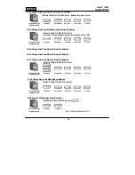
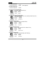
Страница 14: ...ccess Cards RF CARD ONLY MODE Configuration Card Command Cards to be registered Configuration Card 12 12 Add User Access Cards RF CARD PIN MODE Configuration Card Command Cards to be registered Config...

Страница 15: ...e Mode 50 Door Relay 01 OM 51 EX2 Activate Alarm Relay TTL only in Secure mode Secure Mode 00 Alarm Relay TTL 06 OM 06 tt tt is the activating time value seconds from 01sec to 99sec tt value 00sec mea...

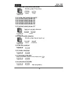
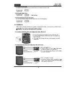
Страница 16: ...TTL time Configuration PIN 12 25 Change Alarm Time When AUX Input 1 Detected 12 26 Change Alarm Time When AUX Input 2 Detected 12 27 Change Alarm Time When AUX Input 3 Detected Refer to Table 1 for OM...

Страница 17: ...et By Command 27 Outputs set by command will be tested Configuration Card Command Configuration PIN 12 39 Change Chime Bell Activating Time tt 00 99 sec Default Chime Bell time 05 sec Configuration Ca...

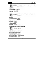
Страница 18: ...or Contact Configuration Card Configuration PIN 12 51 Disable Melody Sound Configuration Card Configuration PIN 12 52 Enable Melody Sound Configuration Card Configuration PIN Default setting Enable 12...

Страница 19: ...lling edge of Exit Button input Default setting Configuration Card Configuration PIN 12 69 Set Door Contact Sensor Input Detection from L to H Door Contact input is detected on the rising edge of Door...

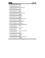
Страница 20: ...tect Door Contact Sensor refer to 12 24 for Alarm time settings Configuration Card Command Door Open time out Configuration PIN 12 82 Set Number of Times of Try Out NN 00 99 times Default Try out numb...

Страница 21: ...e function on the unit WARNING You may lose all setup data after Initialization 13 1 Hardware Initialization When the Configuration Card or PIN is lost 13 2 Wire Initialization When the Configuration...

Страница 22: ...ant to Part 15 of the FCC Rules These limits are designed to this equipment generates uses and can radiate radio frequency energy and if not installed and used in accordance with the instructions may...

Страница 23: ...is in the normal operation mode It is caused by system malfunctions Try turning the power of 100W off and on If the problem still persists initialize the product See 13 Initialization for more informa...

Страница 24: ...ete the User Access Card s e Press PIN ENT Repeat this process if there re more than one card to delete f Present the Configuration Card or press the Configuration PIN ENT Lost the Configuration Card...

Страница 25: ...the Configuration PIN ENT 2 Enter 73 ENT to enable Keypad Input To Enter ID Number See 12 Setting Changes for more details If the buzzer does not beep 1 If the buzzer beeps after a certain length of...

Страница 26: ...connected to the Exit Button If the 100W responds when the exit button is pressed replace the exit button because it is faulty If the 100W does not respond the 100W is malfunctioning Initialize the pr...

Страница 27: ...ith a measuring instrument check if any noise is present in the communication cable If a trace of noise is detected enhance the GND signal by using the shield wire and a spare wire of the cable as GND...

Страница 28: ...wiring between the door lock and the 100W to see if there is any short circuit or cutoff 2 Check the operation of the door lock Remove the door lock from the 100W and check the relay output from the...

Страница 29: ...property is located where this product will be used it would be extremely difficult to determine the actual damages that may result from a failure of the product to perform as anticipated and the low...

Страница 30: ...tion Code 1 Company Name 2 Model Name 3 Serial No 4 Original Invoice No 5 Distributor 6 Purchasing Date 7 RMA Request Date Please check your problems Card Reading Power Keypad Communication Relay LCD...

Страница 31: ...31 17 Template MEMO...

Страница 32: ...00WHE1X The specifications contained in this manual are subject to change without notice at any time 5F Ace Techno Tower B D 684 1 Deungchon Dong Gangseo Gu Seoul 157 030 Korea Tel 82 2 2659 0055 Fax...

Отзывы: