INSTALLATION OF THE PRODUCT
p.21
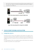
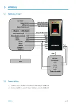
You can use separate power supplies for the LX006/SR and the Controller; howeve
r, the GND(-) wire must be connected to the Black wire, in any case.
5.3
INPUT WIRING
External LED Control Connection
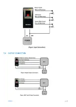
Connect the LED Control Input wire (Blue wire with White stripe) to the NO port of controlle
r relay output, and GND to the COM port. Set I/O of the controller; then you can control tun
ing on and off the green LED. While the LED control is working, the green LED stays on.
The controller can use the I/O setting to set the LED controller so that it displays the addition
al LED status for authorized/unauthorized access. For more information about the I/O settin
g of the controller, refer to the controller’s user manual.
External Buzzer Control Connection
Connect the Buzzer Control Input wire (White wire with Red stripe) to the NO port of contro
ller relay output, and GND to the COM port. Set I/O of the controller; then you can generate
beep sound. While the buzzer control is working, the product keeps sounding beep.
The controller can use the I/O setting to set the buzzer controller so that it sounds the additi
onal beep for authorized/unauthorized access. For more information about the I/O setting o
f the controller, refer to the controller’s user manual.
External Input Device Connection (System Operating Mode Change through Extern
al Input)
Connect the System Mode Control wire (Gray wire with Red stripe) to the NO port of contro
ller relay output, and GND to the COM port. Set I/O of the controller; then you can control t
he system mode. While the system mode is controlled, RF Only mode is operated.
With I/O or time schedule setting, the controller can switch system operation mode in a spec
ific time section. For more information about the I/O setting of the controller, refer to the co
ntroller’s user manual.
Содержание LX006
Страница 1: ......
Страница 15: ...PRODUCT EXPLANATION 5 p 10 1 PANEL LAYOUT...
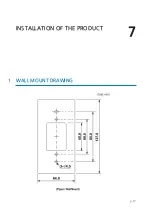
Страница 22: ...INSTALLATION OF THE PRODUCT 7 p 17 1 WALL MOUNT DRAWING...
Страница 27: ...p 22 WIRING 5 4 OUTPUT CONNECTION...
Страница 33: ...p 28 TCP IP COMMUNICATION PORT CONNECTION...
Страница 44: ...OUTPUT FORMAT p 39 2 ABA TRACK SELECTABLE USING THE SOFTWARE 2 1 Data format 2 2 Output timing 3 OUTPUT MODE...
Страница 45: ...p 40 OUTPUT MODE 3 1 NORMAL OUTPUT MODE 3 2 EXTENSION OUTPUT MODE SET BY APPLICATION SOFTWARE...
Страница 49: ...p 44 How to register fingerprint 2 How to register fingerprint...


