p.14
Operation
If you enter a 1-8 digit PIN,
① 1234ENT Wiegand 00001234
RS232 00001234
② 12345678ENT Wiegand 12345678
RS232 12345678
4.
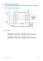
Burst + RS232 Output Format
I.
When you set output to Burst + RS232 format and press numeric keys on the keyp
ad, you can hear a beep sound and the green LED turns on indicating PIN entry sta
rt.
II.
When you set output to Burst + RS232 format, PIN data sends 8bit Burst format if
you press numeric keypad. And if you enter <ENT> key with 1 to 8 digit of keypad,
PIN data sends RS232 format. In case of RS232 output format, if you do not finish
PIN entry with “ENT” key and/or if you do not press any keypad for 5 seconds, clear
PIN data (no output) and return to normal mode.
5.
LED Control:
You may change the behavior of the red, green and yellow LEDs as follows;
I.
To keep the red LED turned off, connect the LED control in wire (white with red str
ipe) to the GND.
II.
To keep the green LED turned on, connect the LED control in wire (yellow wire) to
the GND.
III.
To keep the yellow LED turned on, connect the LED control in wire (Blue with whit
e Stripe wire) to the GND. For more information, please refer to 8. Wire Connectio
n to Access Controller on Page 9.
6.
Beeper Control:
In normal operation, the reader sounds one beep when it reads a proximity card.
However additional beeps can be sounded to improve indication for access status (grant
ed or denied) by wiring blue wire of the beeper control input to system ground level.
The beeper will remain on as long as the blue wire is connected to system ground.
7.
Tamper Switch
The RFK101 / IPK101has normal close (NC) type Tamper Switch. When the unit is install
ed with wall mount, the tamper switch output wires, the gray wire (COM) and the gree
n with white stripe
wire (NC) will be short circuits. When the unit is removed from the wall mount, the tam
per switch output wires will be open circuits.
3.2
Advanced Operation (Optional)


