11
10
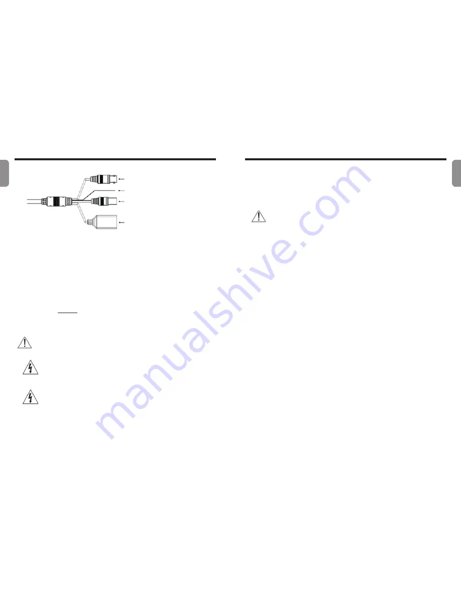
Cable
• BNC Video Out (Yellow):
Connect the monitor. Use these ports for previewing
video and not monitoring video.
• FGND (Frame Ground):
Used to ground the device.
• Power In (Red):
Connect to the power adapter (12 VDC).
• Network Port:
Connect a network cable with an RJ-45 connector to this port. If using
a PoE switch, you can supply power to the camera using an ethernet cable. For more
information on PoE switch use, refer to the switch manufacturer’s operation manual. You
can configure, manage, and upgrade this camera and monitor its images from a remote
computer over the network. For more information on network connection setup, refer to
the IDIS Discovery
manual.
☞
Check your local laws and regulations on making video or audio recordings. The user
will be held liable for any violation of the law.
PoE power is not supported during IR LED operation.
When switching over from 12 VDC to PoE as the power source,
the system will be rebooted once the power adapter is disconnected.
Organize the power cable so that it will not cause people to trip over
or become damaged from chairs, cabinets, desks, and other objects
in the vicinity. Do not run the power cable underneath carpet or a rug
or plug the cable into a power outlet shared by a number of other
devices.
Factory Reset
If you turn the lid on the bottom of the product counterclockwise, there is a factory reset
switch.
This will only be performed remotely on the rare occasions that you want to return all
settings to the original factory settings.
A factory reset will clear all camera settings configured by the user.
For detailed camera settings, refer to the camera operation manual and it can be
downloaded from our website : www.idisglobal.com
①
②
③
④
①
BNC Video Out(Yellow)
②
FGND(Frame Ground)
③
Power In(Red)
④
Network Port
English
English


