Part 1 – Introduction
8
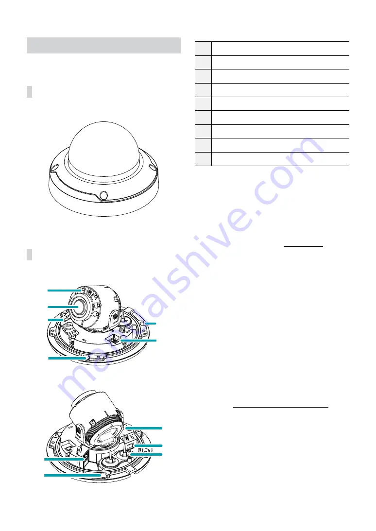
Overview
Dome Cover
Body
1
2
3
6
5
5
9
0
!
5
7
1
IR LED
2
Lens
3
Factory Reset Button
5
Wall/Ceiling Installation Hole
6
Power
7
Network Port
9
Alarm I/O, Audio I/O
0
SD Memory Card Slot
!
Cable Rubber
•
IR LED
A sensor in the middle monitors lighting levels and
activates the IR LED during low-lighting conditions.
•
Lens
A motorized focus and zoom lens is installed.
•
Factory Reset Button
Restores the camera's default factory settings. For
more information, refer to the
.
•
Wall/Ceiling Installation Hole
Used to screw the camera in place on a wall or a
ceiling.
•
Power (DC12V)
Connect this to the power adapter. A A-type jack
is used for the power adapter. (External diameter x
internal diameter: 5.5 x 2.5)
•
Network Port
Connect a network cable with an RJ-45 connector to
this port. If using a PoE switch, you can supply power
to the camera using an Ethernet cable. For more
information on PoE switch use, refer to the switch
manufacturer's operation manual. You can configure,
manage, and upgrade this camera and monitor its
images from a remote computer over the network.
For more information on network connection setup,
refer to the
IDIS Discovery operation manual
.


