background image


59 


©Godiva  Ltd.  Our  policy  is  one  of  continuous  development.  We  therefore  reserve  the 
right to amend specifications without notice or obligation. 


Figure 1E (based on PC2_4010) 


Содержание Godiva Prima SmartCAFS PC1 Series

Страница 1: ...3 5 0 or 6 5 and SmartCAFS200 from September 2010 Installation and Operation Manual Godiva Ltd A Unit of IDEX Corporation Charles St Warwick CV34 5LR England 44 0 1926 623600 44 0 1926 623666 623689 w...

Страница 2: ...mber 2011 28 Additional diagram Compressor Oil Water separator location relationship Issue 3 4 April 2012 10 Gearbox oil capacity now 1 2 litres Issue 4 5 April 2012 46 CAFS mixing manifold greasing b...

Страница 3: ...10 COMPRESSOR 10 PUMP GEARBOX 10 PUMP BEARING HOUSING 10 MODEL IDENTIFICATION SYSTEM 10 RECOMMENDED FOAM AGENTS 11 HALE FOAMLOGIX MODELS 3 3 5 0 6 5 CAN BE USED WITH THE FOAM CONCENTRATES SPECIFIED O...

Страница 4: ...ND INITIAL SET UP FOAMLOGIX 3 3 5 0 6 5 36 OPERATION 37 FOAMLOGIX CONTROL PANEL FUNCTIONS 37 COMMISSIONING START UP PROCEDURE 37 CALIBRATION OF FOAMLOGIX 38 SMART SWITCH OPERATION 38 WET AND DRY BUTTO...

Страница 5: ...ING FAULTS CAFS 50 AIR INJECTION FAULTS 51 RECOMMENDED SPARES KIT FOR BI ANNUAL SERVICE 54 NOTES 54 INSTALLATION DRAWINGS PC2_ WITH SMARTCAFS200 55 FIGURE 1A BASED ON PC2_4010 55 FIGURE 1C BASED ON PC...

Страница 6: ...mLogix 3 3 5 0 and 6 5 Foam Proportioning Systems MDTII Manual Dual Tank Selector Compressor and Intelli tank Water foam level display unit please see the separate manuals supplied IMPORTANT NOTES Ple...

Страница 7: ...nts apply to pumps driven by petrol diesel or other means DO NOT OPERATE the unit close to flammable materials or structures DO NOT SMOKE while operating the unit DO NOT inhale fumes or gases Avoid pr...

Страница 8: ...AL PROTECTION It is prohibited to pour engine oil and other contaminants onto the ground down sewers drains or into water courses Dispose of lubricants through authorised waste disposal contractors li...

Страница 9: ...m Compatible Manufacturer Hale Products Inc Model FoamLogix 3 3 Type Electronic foam proportioning system Operating voltage 12 and 24 volt systems available Fuse rating 12V 24V 60 40 amp Current draw...

Страница 10: ...oil Capacity 12 litres Pump Gearbox Recommended BP Energol GR XP 68 or similar Capacity 1 2 litres approximately Pump Bearing Housing Recommended 10W 40 or 15W 40 Multi grade engine oil Capacity 1 0 l...

Страница 11: ...ale Bulletin 650 Rev 32 7 17 07 The foam concentrates in the list have been tested by Hale Products to ensure compatibility with FoamLogix systems This information is intended to assist the end user i...

Страница 12: ...meter This unit is primarily of interest to service technicians for CAFS fault diagnosis The device is located on the left side of the pump PTO driven Gearbox with compressor drive via an electromagne...

Страница 13: ...nt Group Note Hale FoamLogix 3 3 5 0 or 6 5 foam pump is supplied loose for mounting by vehicle builder FoamLogix 3 3 shown Dual Tank Selector mandatory option Literature Pack Dual Tank Selector Exten...

Страница 14: ...uge Tank A 9 Foam tank level gauge Tank B if fitted 10 Foam On indicator 11 Air Enabled indicator 12 Solution or CAFS selector switch 13 Top Compressor temperature warning light Bottom Air inject on 1...

Страница 15: ...rate cannot be introduced unless water is flowing through the unit Compressed air cannot be introduced unless foam concentrate is flowing 2 Slugging unmixed air and water in the discharge line is prev...

Страница 16: ...ix Foam Proportioning System The FoamLogix system consists of three main components 1 Foam Pump Motor Assembly 2 Control Panel integral with main pump control panel 3 Flow measurement and injection ma...

Страница 17: ...out notice or obligation INSTALLATION AND INITIAL SET UP The following connection points should be considered when installing the PC1_ or PC2_ assembly into a vehicle Lifting Points Secure handling of...

Страница 18: ...stem Remote Mounted Model 3 3 shown Inlet from foam tank Models 3 3 5 0 19mm 3 4inch NPT Model 6 5 25 4mm 1inch NPT Note foam tank must be located above FoamLogix unit Also refer to installation notes...

Страница 19: ...mend specifications without notice or obligation Fluid Drain Points Pump bearing housing and gearbox oil drain points are located at the lower left side of the pump viewed from the suction tube end Ge...

Страница 20: ...led with the correct quantity and specification before starting the pump Bearing Housing The oil filling point for the pump bearing housing is located on the right side of the pump viewed from suction...

Страница 21: ...the vertical position an oil fill point and oil level check point are located on both sides of the housing Fill the gearbox until the oil flows from the oil level check point This is the only accurate...

Страница 22: ...etail Fill the gearbox until the oil flows from the oil level check point This is the only accurate method of checking that the correct amount of oil has been added to the gearbox as it allows for dif...

Страница 23: ...ecified deflection and secure PTO drive flange connection Various specifications available Compressor Drive Belt The compressor is driven by a Goodyear Eagle PD synchronous drive belt The installer mu...

Страница 24: ...mend specifications without notice or obligation Separator Tank for Compressor Oil Note Separator must be installed in the vertical position as shown Pipework from compressor to oil tank must be arran...

Страница 25: ...nstituency 1 Install the system as directed 2 Run the system at normal operating pressure discharge compressed air foam through the most restrictive line typically a hose reel 3 Set the SmartCAFS ARC...

Страница 26: ...26 Godiva Ltd Our policy is one of continuous development We therefore reserve the right to amend specifications without notice or obligation Schematic CAFS Fluid...

Страница 27: ...EHICLE 6 mm CONNECTOR OEM CONNNECTION COMPRESSOR OIL INLET G 3 VICTUALIC 3 VICTUALIC FOAM INLET 14 NPT DRY SETTING BYPASS CAFS MIXER INSERT RETAINED IN POSITION BY VICT UALIC AIR INLET 1 BSP A3 CAFS O...

Страница 28: ...he relationship between compressor air oil outlet and separator air oil inlet connections when installing A B A B 300 50 950 212 5 350 62 5 1000 225 400 75 1050 237 5 450 87 5 1100 250 500 100 1150 26...

Страница 29: ...tion on rear of compressor 2 Air supply from separator tank to compressor 6mm tubing connector 3 Air pressure for pump functions connect from vehicle supply with 6mm tubing 3 1 High Pressure discharge...

Страница 30: ...CAN COMMUNICATION POS CIRCUIT COLOR G A A CAN H IGH YELLOW 1033 49 B CAN LOW GREEN 1033 49 C CAN SHIELD BL ACK 1033 49 C14 COMPRESSOR CLUTCH POS CIRCUIT COLOR GA A C LUTCH BLU 16 B GROU ND BLK 16 C21...

Страница 31: ...t Colour GA 1 Ground 2 Black 16 C15 Pos Circuit Colour GA 1 Ground 1 Black 16 C14 Pos Circuit Colour GA 1 Power Pink 18 2 Can high Yellow 18 3 Can Shld Black 18 4 Ground 1 Black 16 5 Can Low Green 18...

Страница 32: ...t Colour GA 1 SW No Orange 18 2 Remote LED Red 18 3 Remote LED Blue 18 4 SW Common Black 18 Requires connection to foam pump C3 Pos Circuit Colour GA 1 GND Ref PAD WHL Black 18 2 Pos Ref PAD WHL Red 1...

Страница 33: ...R R T HROTT LE R 2 3 4 6 8 B G 2 2 3 3 1 1 R B RED BLACK G Y GREEN YELLOW N B BROWN BLACK K PINK R RED S LIGHT GREY W B WHITE BLACK W R WHITE RED N S BROWN LIGHT GREY N W BROWN WHITE N U BROWN BLUE W...

Страница 34: ...ts Foam Tank to Foam Pump The foam feed line must not at any point be lower that the foam pump and be fitted with an isolating tap for maintenance purposes The isolating tap should be located as close...

Страница 35: ...ompatible with those foam concentrates used Brass or 300 series stainless steel are suitable The areas containing the PC2_ or PC1_ components must be adequately shielded from the ingress of road spray...

Страница 36: ...ON AND INITIAL SET UP FOAMLOGIX 3 3 5 0 6 5 For foam pump installation please refer to the FoamLogix Model 3 3 5 0 6 5 Description Installation and Operation manual part number 029 0021 68 0 supplied...

Страница 37: ...To prevent unnecessary operation of the pump priming system maintain an idle speed of 900 1000rpm FoamLogix Control Panel Functions Commissioning Start Up Procedure 1 Check that all the necessary con...

Страница 38: ...the Fault Finding chart on page 44 10 For 3 3 5 0 6 5 FoamLogix select tank B and repeat the priming procedure for that tank 11 When prime is achieved deselect simulated flow by pressing both up down...

Страница 39: ...will start the FoamLogix and send the Air Ratio Control valve to its respective pre set Note the Air Ratio Control Valve can only be controlled when in CAFS mode Configure the WET and DRY presets The...

Страница 40: ...nd the Air Ratio Control valve to the extreme WET position Operating the PC2_ or PC1_ from a Vehicle Water Source 1 Connect a suitable delivery hose and branch to the CAFS discharge 38 to 45mm diamete...

Страница 41: ...d run the pump at idle until a vacuum of approximately 0 5 bar is achieved and then slowly open the tank to pump valve Optional Tank Selection for FoamLogix 3 3 5 0 6 5 For specific detail please refe...

Страница 42: ...PRESSURE TO PUMP SUCTION WHEN OPERATING CAFS 1 Set the water pump to idle 2 Select CAFS by pressing the top of the CAFS selector switch marked CAFS If pump speed is 2400rpm or compressor pressure is 1...

Страница 43: ...compressor oil temperature reach 105o C a control panel warning indicator will illuminate The compressor can sustain 105 C for short periods without damage 2 If the compressor oil temperature reaches...

Страница 44: ...mLogix manual Operate the system in bypass to move the concentrate and prevent gelling if concentrate is left in the system without use for three months See FoamLogix manual EVERY 12 MONTHS PC1_ PC2_...

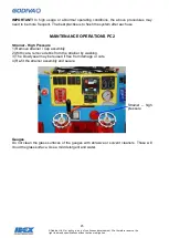
Страница 45: ...ractise is to flush the system after each use MAINTENANCE OPERATIONS PC2 Strainer High Pressure 1 Remove strainer Cap assembly 2 With care remove debris from the strainer by washing 3 The Dowty seal m...

Страница 46: ...est Place the blanking cap s in position on the inlet s of the pump and close the delivery valves Run the pump at 1300 1500 rpm and observe the vacuum compound needle When a vacuum of 0 7bar is obtain...

Страница 47: ...mer end cap The priming valve diaphragm Thermal Relief Valve TRV Test if option fitted With the pump primed close all discharges Run the pump with high pressure selected at approximately 2800rpm to pe...

Страница 48: ...notice or obligation FAULT FINDING PUMP OPERATING FAULTS 1 LOSS OF SUCTION Do a Pressure Test Do a Vacuum Test No Yes No Yes Loss of Suction All suction connectio ns air Tighten all connections Sucti...

Страница 49: ...ligation PUMP OPERATING FAULTS 2 EXCESSIVE PUMP NOISE No Pump makes excessive rattling noise during operation Probably due to pump cavitation Decrease pump speed Has noise disappeared Yes Continue usi...

Страница 50: ...FAULTS CAFS No Foam Solution FoamLogix not operating Switch on FoamLogix No concentrate in foam tank Foam pump not primed Refill the foam tank Prime the foam pump Compressor Overheating No water supp...

Страница 51: ...on AIR INJECTION FAULTS No No Air Injection Is FoamLogix turned on Turn on FoamLogix and set the required Is CAFS turned on Turn on CAFS Is compressor running Check drive belt Is Foam Low Level Switch...

Страница 52: ...FoamLogix Manual Replace the solenoid valve Replace interlock control module Yes No No No Continued from previous page Is solenoid seeing 12 24V and common at connection Press test button on solenoid...

Страница 53: ...ation Godiva Prima pump illustrated parts list Please refer to Godiva Ltd publications PC2 model GP 258 Compressor illustrated parts list Please refer to Gardener Denver Enduro 12 manual Foamlogix ill...

Страница 54: ...rive 61198 002 PC2_ PC1_ AR Strainer Hi Pressure 60051 Not PC1_ series 4 Washer Dowty Oil drain UFP 2303 08 2 Washer Dowty High Pressure strainer UFP 2303 15 Common part 2 Washer Dowty NRV Inlet UFP 2...

Страница 55: ...va Ltd Our policy is one of continuous development We therefore reserve the right to amend specifications without notice or obligation INSTALLATION DRAWINGS PC2_ WITH SMARTCAFS200 Figure 1A based on P...

Страница 56: ...56 Godiva Ltd Our policy is one of continuous development We therefore reserve the right to amend specifications without notice or obligation Figure 1B based on PC2_4010...

Страница 57: ...57 Godiva Ltd Our policy is one of continuous development We therefore reserve the right to amend specifications without notice or obligation Figure 1C based on PC2_4010 See page 64...

Страница 58: ...58 Godiva Ltd Our policy is one of continuous development We therefore reserve the right to amend specifications without notice or obligation Figure 1D based on PC2_4010...

Страница 59: ...59 Godiva Ltd Our policy is one of continuous development We therefore reserve the right to amend specifications without notice or obligation Figure 1E based on PC2_4010...

Страница 60: ...60 Godiva Ltd Our policy is one of continuous development We therefore reserve the right to amend specifications without notice or obligation Figure 1F based on PC2_4010...

Страница 61: ...61 Godiva Ltd Our policy is one of continuous development We therefore reserve the right to amend specifications without notice or obligation Figure 2A Manifold...

Страница 62: ...62 Godiva Ltd Our policy is one of continuous development We therefore reserve the right to amend specifications without notice or obligation Figure 2B Manifold...

Страница 63: ...uous development We therefore reserve the right to amend specifications without notice or obligation Figure 3A Cooling Cool water supply inlet from pump Oil outlet to compressor Water return to pump s...

Страница 64: ...64 Godiva Ltd Our policy is one of continuous development We therefore reserve the right to amend specifications without notice or obligation Figure 3B Cooling...

Страница 65: ...65 Godiva Ltd Our policy is one of continuous development We therefore reserve the right to amend specifications without notice or obligation Figure 4A Oil Separator...

Страница 66: ...66 Godiva Ltd Our policy is one of continuous development We therefore reserve the right to amend specifications without notice or obligation Figure 4B Oil Separator See page 55...

Страница 67: ...d Our policy is one of continuous development We therefore reserve the right to amend specifications without notice or obligation Figure 5A FoamLogix Dimensions Fig 5B FoamLogix Baseplate mounting hol...

Страница 68: ...name US Forestry Service Approved ANSUL Silvex Class A Foam Concentrate Angus Forexpan S 0 1 1 0 Chubb National Foam 1st Defense Class A Coldwater Foam Chubb National Foam Knock Down Monsanto Phoschec...

Отзывы: