B-2048-1(1)
INSTRUCTION SHEET - HS1T Series
Solenoid Type Safety Switch
( 2 / 9 )
2019.07
3
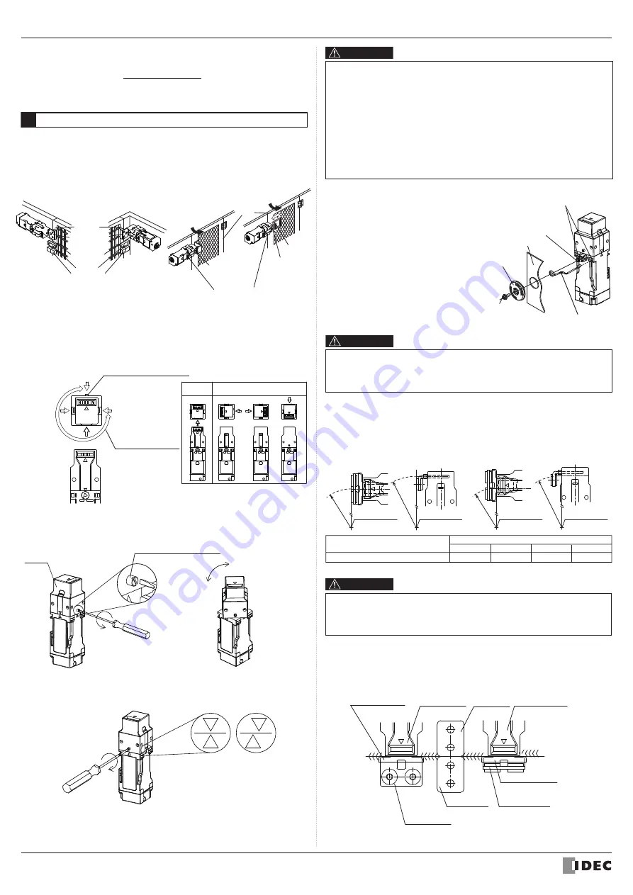
Mounting Examples
• Install the interlock switch on the immovable machine or guard, and install the
actuator on the movable door. Do not install both interlock switch and actuator on
the movable door, otherwise the angle of insertion of the actuator to the safety switch
may become inappropriate, and failure will occur.
(Examples of Mounting on Sliding Doors)
HS9Z-A11T
Actuator
Door Stop
Latch
HS1T
Safety Switch
Door
(Examples of Mounting on Hinged Doors)
HS9Z-A12T
Actuator
HS1T
Safety Switch
HS9Z-A12T
Actuator
Door
●
The HS1T Head
• Changing the Mounting Directions of the HS1T Head
The head of the HS1T can be changed in four directions by pulling up the rota-
tion stopper screw of the HS1T head with a minus driver.
The head rotates in the range of movement as in the diagram below, based on
the mounting direction at the time of shipment.
When
Shipped
Alternative Mounting Direc ions
Range of Movement
of the Head
Attachment Direction
at the Time of Shipment
Rotation Stopper Screw
●
How to Change the Mounting Direction
①
Rotate the minus driver in he direction
of the arrow and pull up the rotation
stopper screw.
②
Once you've pulled up the rotation stopper
screw to its stopping point, rotate the head
to your desired direction.
③
When the head has been rotated to your desired mounting direction, align
the
△
marks of the head and case, and then tighten the rotation stopper screw.
Head
R1
R2
R4
R3
Rotation Stopper Screw
○
×
Latch
Fzh
=
maximum force (F1max.)
Safety coefficient (=1.3)
CAUTION
• After installing the rear unlock button, apply Loctite to the screw so that the screw
does not become loose. The lod is made of stainless steel.The rear unlock button
is glass-reinforced PA66 (66 nylon). The mounting screw is iron. Take the
compatibility of plastic material and Loctite into considera ion.
HS9Z-A12T
R1
510 mm
R2
840 mm
R3
270 mm
R4
450 mm
Minimum Radius
CAUTION
• The values shown above are based on the condition that the actuator enters and
exits the actuator entry slot smoothly when the door is closed or opened. Since
there may be deviation or dislocation of the hinged door, make sure of correct
operation in the actual applica ion before installation.
Actuator Mounting Reference Position
As shown below, the mounting reference position of the actuator inserted into the
safety switch is:
(After mounting the actuator, remove the actuator stop from the safety switch.)
• When using the safety switch for a hinged door, the minimum radius of the applicable
door is shown in the following figures.
Minimum Radius of Hinged Door
• Insert the rear unlock indicator
(supplied) in the indicator guide hole on
either the left or right side of the safety
switch and attach the ring part to the
rod on the rear side. After installing the
safety switch on the panel, put the rear
unlock button (supplied) on the rod,
and fasten using the mounting screw
(supplied).
When installing on the aluminum frame
with a thickness of 6mm or more, use
the rear unlock button for the frame kit
(HS9Z-FL5□) sold separately.
The Rear Unlock
Button
Mounting
Screw
(M3 sems screw)
Panel
Rod
When the center of the hinged door is
on the extension line of the actuator
mounting surfase.
When the center of the hinged door is
on the extension line of the contact surface
of actuator and safety switch.
Door Hinge
Door Hinge
Minimum
Radius
Minimum Radius
Door Hinge
Door Hinge
Minimum Radius
Minimum
Radius
ActuatorCover
Door Stop
Safety Switch
Safety Switch
HS9Z-A11T
Actuator
HS9Z-A12T
Actuator
Door Stop
ActuatorCover
*5 F1max is maximum force. The actuator’s guard-locking force Fzh is calculated in
accodance with GS-ET-19:
*6 Make sure that a fast acting fuse for short-circuit protection trips before
overheating of the wires.
●
Mounting Directions of the HS1T Head
• There is a range of movement to the head. Do not forcibly rotate the head
over its range of movement. There is a risk of damage.
• There is a risk of damage if the rotation stopper screw is forcibly tightened
without aligning the
△
marks of the head and case.
• Apply loctite or the like to on the rotation stopper screw to prevent loosening.
• When replacing the HS1T head, make sure that no foreign object enters
into the safety switch.
• Tighten the rotation stopper screw of the head tightly, otherwise the safety
switch may malfunction.
• Don't loosen the rotation stopper screw of the head except when the
mounting directions of the head is changed.
Rear Unlock
Indicator
Indicator Guide Hole
WARNING
Installing the Rear Unlock Button and Indicator
(Type HS1T-
□
L)


