background image

8

Harrier GTE - 

Installation & Servicing

GENERAL

7

SEALED (PRESSURISED) SYSTEMS

6

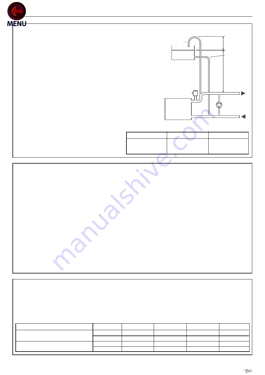
OPEN VENTED SYSTEM REQUIREMENTS - minimum static head requirements

The Harrier GTE boiler has a minimum static head requirement of
2.5 metres (8 feet approx.) depending on the particular
characteristics of the system design (see diagram).  The
information provided is based on the following assumptions.

1. An open vent/safety pipe connection is made immediately after

the flow connection.

2. A cold feed/expansion pipe connection is made to the system

return pipe within 0.75m of the boiler return connection.

3. The maximum flow rate through the boiler is based on a

temperature difference of 11ºC (20ºF) at full boiler output with
the circulating pump positioned in the flow of the system.

4. The boiler is at the highest point of the system.  Systems

designed to rise above the flow connections will, of course,
automatically require a minimum static head higher than
shown.

5. The position of the open vent/safety pipe above the expansion

cistern water level is given as a guide only.  The final position
will depend upon particular characteristics of the system.
Pumping over of water into the expansion cistern should
be avoided.

6. Both open vent/safety pipe and cold feed/expansion

pipes must be of adequate diameter to suit the output of
the boiler (see table below).

Working pressure 6 bar maximum.

Particular reference should be made to BS. 6644: Section 2;
Subsection 11 and Guidance note PM5 "Automatically
controlled steam and hot water boilers" published by the
Health and Safety Executive.

The information and guidance given below is not intended to
override any requirements of either of the above publications
or the requirements of the local authority, as or water
undertakings.

In general commercial closed pressurised systems are
provided with either manual or automatic water make up.

In both instances it will be necessary to fit automatic controls
intended to protect the boiler, circulating system and ancillary
equipment by shutting down the boiler plant if a potentially
hazardous situation should arise.

Examples of such situations are low water level and operating
pressure or excessive pressure within the system.
Depending on circumstances, controls will need to be either
manual or automatic reset.  In the event of a shutdown both
visual and audible alarms may be necessary.

Open vent
safety pipe

750mm

Cold feed/
expansion pipe

H = 2.5m

To
pump

Pressure

relief

valve

FLOW 

RETURN 

Shunt pump
(if required) 

Note: Height, H, MUST be
increased if necessary to
comply with the min.
head required by the
pump manufacturer

BOILER

This diagram does not show safety valves & water
flow switches etc necessary for safe operation 

Expansion

cistern

har5966

Expansion vessels used must comply with BS. 4814 and must
be sized on the basis of the total system volume and initial
charge pressure.

Initial minimum charge pressure should not be less than 0.5
bar (7.2psi) and must take account of the static head and
specification of the pressurising equipment.  The maximum
water temperatures permissible at the point of minimum
pressure in the system are specified in Guidance Note PM5.

When make up water is not provided automatically it will be
necessary to fit controls which shut down the plant in the event
of the maximum system pressure approaching to within
0.35bar (5psi) of the safety valve setting.

Other British Standards applicable to commercial sealed
systems are:

BS. 6880: Part 2

BS. 1212

BS. 6281: Part 1

BS. 6282: Part 1

BS. 6283: Part 4

8

SYSTEM DESIGN

Minimum Water Flow

Design Flow Rates

The following table gives the flow rate required for each boiler
based on a design temperature difference of 11ºC (20ºF) at the
maximum rated output.  For hydraulic resistance see
Performance Data table (page 2).

Minimum Flow Rates

It may be necessary to fit a shunt pump to ensure minimum
flow rates.

Boiler Output kW

Open Vent (mm)

Cold Feed (mm)

60 to 150

32

25

151 to 300

38

32

301 to 600

50

38

Boiler Size

GTE 5

GTE 6

GTE 7

GTE 8

GTE 9

Normal water flow rate

l/s

3.04

3.91

5.00

6.08

7.17

temperature difference 11ºC (20ºF)

g.p.m.

40.1

51.6

66.0

80.2

94.6

Minimum water flow rate

l/s

0.96

1.23

1.57

1.91

2.25

temperature difference 35ºC (63ºF) g.p.m.

12.7

16.2

20.7

25.2

29.7

For latest prices and delivery to your door visit MyTub Ltd - 0845 303 8383 - www.mytub.co.uk - [email protected]

Содержание Harrier GTE 5

Страница 1: ...re parts that you can be assured conform to the safety and performance specification that we require Do not use reconditioned or copy parts that have not been clearly authorised by Ideal Boilers Harri...

Страница 2: ...es unless covered by these Installation and Servicing Instructions or as otherwise recommended by Caradon Ideal Limited in writing If in doubt please enquire Any direct connection of a control device...

Страница 3: ...aintenance fuel flexibility and low emissions Suitable for oil or gas operation the Harrier GTE range is supplied in a choice of 5 standard models rated in outputs from 105kW 358 000 Btu h to 330kW 1...

Страница 4: ...73 23 EEC Low voltage directive Relevant standard is EN60335 1 89 336 EEC Electromagnetic Compatibility Directive Relevant standards are EN50081 1 EN50082 1 and EN55014 90 396 EEC Gas Appliance Direc...

Страница 5: ...mately result in premature radiator failure Open vented systems are not completely sealed from the atmosphere if proper venting and expansion of system water is to be achieved The same tank is used to...

Страница 6: ...flue connections and access to the flue sample point drain connection flue and smokehood cleanout doors and any safety or control devices Sides One side may be 100mm the other side must be 200mm plus...

Страница 7: ...acent communicating room can in certain conditions adversely affect the safe operation of the boiler Where such a fan is already fitted or if it is intended to fit an extractor fan after installation...

Страница 8: ...ituation should arise Examples of such situations are low water level and operating pressure or excessive pressure within the system Depending on circumstances controls will need to be either manual o...

Страница 9: ...e 4 Flow switch if necessary 5 Air separator 6 Automatic venting valve 7 Valve 8 Shunt pump required for all models 9 Expansion tank 10 Draining valve 11 Sludge valve 12 Mixing valve 13 Non return val...

Страница 10: ...nd IGE UP 10 whilst BS 5410 Pt 1 similarly applies to OIL fired boilers The table below contains the minimum dimensions of the flue required for each boiler model in order to ensure sufficient draught...

Страница 11: ...crewdriver Wide flat screwdriver 13 and 17mm spanners hammer Silicone glue JDTE assembly tool Simplified assembly tool The assembly of any optional devices purchased with the boiler is described in th...

Страница 12: ...BASE FRAME INSULATION 1 Locate the insulation between the sides and end with the black fabric on the underside 2 2 fal5982 1 1 2 2 har5983 2 Assemble the front and rear components into the ends of the...

Страница 13: ...ection and secure both ends with the 4 washers and M12 nuts This may be conducted after preparing the section Frame 17 and fitting thermocord Frame 18 if preferred 17 PREPARING THE REAR SECTION This m...

Страница 14: ...for intermediate sections 19 ASSEMBLING THE INTERMEDIATE SECTIONS 1 Place the first intermediate section onto the base frame 2 Fit the connections of the intermediate section onto the nipples in the r...

Страница 15: ...N 20 ASSEMBLING THE INTERMEDIATE SECTIONS CONT D Proceed likewise for other intermediate sections A 20 cm har5993 1 3 2 4 5 6 8 7 INSTALLATION For latest prices and delivery to your door visit MyTub L...

Страница 16: ...el the boiler by adjusting its feet 22 PREPARATION FOR FITTING THE FLUE CLEANOUT AND BURNER DOORS FOR RH OPENING 1 Screw in and tighten all the studs in the appropriate tappings as shown for items A a...

Страница 17: ...lue cleanout door hinge bracket as shown and secure with two M12 nut and washers Note For left hand opening position the hinge bracket on the left 4 Position the flue cleanout door in place and insert...

Страница 18: ...s of baffle Use only the 570 mm long ones and discard the shorter ones 4 In all cases the baffles should be pushed in to be flush with the front har5999 3 2 1 25 POSITIONING THE FLUE BAFFLES IN THE LO...

Страница 19: ...nto the upper connection and the plug into the lower connection har7001 1 2 2 27 FITTING THE SMOKEHOOD 1 Screw the four M8 studs into the rear section 2 Put a drop of silicone at about every 100mm of...

Страница 20: ...ain cock with thread sealing tape or compound not supplied 2 Screw the flow and return pipes and the drain cock into the rear section Ensure the tapping on the flow connection faces upwards to accept...

Страница 21: ...8 Connect the pressure system water 9 Open the fill valve 10 Pressurise the boiler Maintain pressure for at least 10 minutes Any drop in pressure indicates a leakage in the boiler body 11 After succes...

Страница 22: ...9 After fitting the front insulation similarly place the rear section 3 Secure the two sections together using the clips provided 4 All Models Place the rear insulation into position ensuring it fits...

Страница 23: ...r edge clips to the crossbars 2 Secure the crossbars to the front and rear section lugs using the M12 bolts washers shakeproof washers and nuts Note the direction of the crossbar to ensure the edge cl...

Страница 24: ...the panel bottom onto the base frame 3 Lift the panel to its vertical position 4 Secure the top edge to the front crossbar support using M8 bolts and shakeproof washers by screwing into the edge clip...

Страница 25: ...washers Note If a pressure relief valve has already been fitted in the flow connector or if the panel is being replaced on a completed installation the top centre piece of the panel may be removed 1 2...

Страница 26: ...panel 2 Route the burner leads through the other opening in the top front panel 3 Lower the control panel onto the location buttons nearer the front and slide the control panel forwards 3 har7018 1 3...

Страница 27: ...right hand opening in the top front panel 2 Route the burner leads through the other openings in the top front panel 3 Lower the control panel onto the location buttons farthest away from the front a...

Страница 28: ...n buttons and slide the panel downwards har7024 41 ASSEMBLING THE REAR TOP PANEL har7025 1 2 2 1 1 Engage the location buttons on the top panel into the keyhole slots in the side panel and slide the p...

Страница 29: ...connection harness The control panel incorporates a boiler thermostat controller a thermometer and a safety thermostat The boiler thermostats one controls the maximum boiler operating temperature The...

Страница 30: ...rews on the rear of the control panel and open the panel 2 Pass the connecting cables to the control panel through the two cut outs in the rear panel of the boiler and route them to the front via the...

Страница 31: ...t via the cable channel s See Frame 35 5 Pass the cables into the control panel through the rectangular openings in the front top panel 6 Secure the cables to the base of the control panel with the ca...

Страница 32: ...pplied har7053 Remove white link wire 50 FITTING OPTIONAL FEATURES FD168 Deluxe Control Panel Hour Run Meters IC8 One or two optional hour run meters stage 1 and 2 may be fitted on the front of the co...

Страница 33: ...TS Safety thermostat VA Alarm indicator VA TS Safety thermostat alarm indicator VB1 Stage 1 operating indicator VB2 Stage 2 operating indicator ZB2 Stage 2 burner switch ZEH Summer Winter switch ZG M...

Страница 34: ...r stage 1 of two stage burners 4 pin plug for stage 2 of the burner Terminal block for connecting to the control panel Note If the electrical characteristics of the burner exceed the following values...

Страница 35: ...l Box Terminal No L1 7 Permanent Live supply from the safety thermostat Burner main supply g y Earth connection Earth connection N 6 Neutral taken after On Off Switch Neutral terminal T1 T2 5 4 Volt f...

Страница 36: ...r two stage burners set 2nd stage 5 C below 1st stage setting Built in stops may be reset See Frame 56 Factory set at 75 C 4 Boiler Thermometer Indicates boiler flow water temperature 5 Flue Gas Therm...

Страница 37: ...tch TESTSTB When held in the pressed momentary use position it tests the safety thermostat Note If two stage burner control fitted operation will continue on 1st stage after 2nd stage cut off AUTO aut...

Страница 38: ...ate Table 1 11 Refer to the burner instructions for specific operating features 12 Set the boiler thermostats 3 or Deluxe model 6 to appropriate settings ensuring the second stage is 5 C lower than th...

Страница 39: ...connect the cable and supply pipe to the burner 5 Open the combustion chamber and flue way doors by removing the 8 nuts 6 Remove the flue way baffles 7 Thoroughly clean the flue ways and baffles 8 Rem...

Страница 40: ...s Check the gas rate and measure the combustion CO CO2 content Complete the boiler log book Carry out functional checks as appropriate 66 SERVICING SCHEDULE To ensure the continued safe and efficient...

Страница 41: ...41 Harrier GTE Installation Servicing NOTES For latest prices and delivery to your door visit MyTub Ltd 0845 303 8383 www mytub co uk info mytub co uk...

Страница 42: ...42 Harrier GTE Installation Servicing NOTES For latest prices and delivery to your door visit MyTub Ltd 0845 303 8383 www mytub co uk info mytub co uk...

Страница 43: ...43 Harrier GTE Installation Servicing NOTES For latest prices and delivery to your door visit MyTub Ltd 0845 303 8383 www mytub co uk info mytub co uk...

Страница 44: ...products The right is therefore reserved to vary specification without notice The Ideal Boilers Technical Training Centre offers a series of first class training courses for domestic commercial and in...

Отзывы: