Ideal Boilers responce 80 Скачать руководство пользователя страница 8

8

Response 80 / 100 / 120 

- Installation

Terminal Position

Minimum Spacing

1.

Directly below or alongside an
opening window, air vent or other
ventilation opening

300 mm (12")

2.

Below guttering, drain pipes or soil
pipes

25 mm

( 1")

3.

Below eaves

25 mm

( 1")

4.

Below balconies or a car port roof

25  mm

( 1")

5.

From vertical drain pipes or soil pipes

25 mm

( 1")

6.

From internal or external corners

25 mm

( 1")

7.

Above adjacent ground, roof or
balcony level

300 mm (12")

8.

From a surface facing the terminal

600 mm (24")

9.

From a terminal facing a terminal

1200 mm (48")

10. From an opening in a car port

(e.g. door or window) into dwelling

1200 mm (48")

11. Vertically from a terminal on the

 same wall

1500 mm (60")

12. Horizontally from a terminal on the wall

300 mm (12")

GENERAL

GAS SUPPLY

The local gas supplier should be consulted, at the installation
planning stage, in order to establish the availability of an adequate
supply of gas. An existing service pipe must NOT be used without
prior consultation with the local gas supplier.

A gas meter can only be connected by the local gas supplier or
by a registered CORGI installer.

Check that the appliance is suitable for the proposed gas supply.
A  working gas pressure of 20 mbar MUST be available at the
boiler inlet.

IMPORTANT.

Installation pipes MUST be fitted in accordance with BS. 6891.
Pipework from the meter to Response boilers MUST be of an
adequate size, i.e. not less than 22mm O.D. copper or
3/4" BSP iron.

The complete installation MUST be tested for gas soundness
and purged as described in the above code.

Table 6 - Balanced flue terminal position

    Approved Manufacturer's Clearance

N.B. 

These clearances are for horizontal flue only.  For vertical

clearances see the publication for Pack K/Pack H.
Note (Positions 2-6)

 : Due to the terminal design, installation

is possible with clearances less than those specified in BS
5440, Part 1.

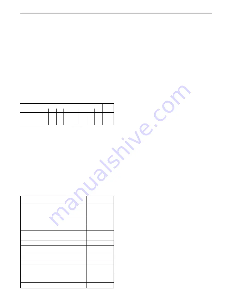
Total length of supply pipe (metres)

Pipe size

9

12

15

20

25

35

40

45

50

(mm Dia.)

Gas

160 140

120

100

89

74.2 67.1 63.6

60

22

Discharge

ft

3

 / h

330 280

250

210 180 151.9 137.7 130.7 123.6

28

FLUE INSTALLATION

The flue must be installed in accordance with the
recommendations of BS. 5440: Part 1.

The following notes are intended for general guidance:

1. The boiler MUST be installed so that the terminal is

exposed to external air.

2. It is important that the position of the terminal allows the

free passage of air across it at all times.

3. Minimum acceptable spacing from the terminal to

obstructions and ventilation openings are specified in
Table 6.

4. Where the lowest part of the terminal is fitted less than 2m

(6'6") above a balcony, above ground or above a flat roof to
which people have access then the terminal MUST be
protected by a purpose designed guard.  The minimum
spacing in Table 6, Nos. 2, 3, 4, 5 and 6 would be 75mm, in
order to allow a terminal guard to be fitted.

Terminals guards are available from boiler suppliers - ask
for  TFC Guard, Model K1. In case of difficulty contact:

Grasslin (UK) Ltd., Tower House, Vale Rise, Tonbridge,
Kent TN9 1TB.  Tel: 01732 359888.  Fax: 01732  354445.
www.ffc.ukco.com

Ensure that the guard is fitted centrally.

5. The flue assembly shall be so placed or shielded as to

prevent ignition or damage to any part of any building.

6. The air inlet/products outlet duct and the terminal of the

boiler MUST NOT be closer than 25mm (1") to combustible
material. Detailed recommendations on the protection of
combustible material are given in BS. 5440: 1990.

7. Where it is essential that the terminal wall plate

 is fitted, i.e.

wall thicknesses over 610mm (24") or with an inaccurately
cut hole, the minimum spacing in Table 6, Nos. 2, 3, 4, 5
and 6 would be 60mm (2.4") in order to allow the terminal
wall plate to be fitted.

IMPORTANT.  It is the responsibility of the installer to ensure, in
practice, that products of combustion discharging from the
terminal cannot re-enter the building or any other adjacent
building through ventilators, windows, doors, other sources of
natural air infiltration, or forced ventilation / air conditioning.

If this should occur the appliance MUST be turned OFF,
labelled as 'unsafe'  until corrective action can be taken.

FLUE LENGTHS

The flue assembly can be adapted to accommodate flue
lengths up to 3 metres for the 80 and up to 4m for the 100 and
120. Refer to Frame 10.

WATER CIRCULATION SYSTEM

The boilers are designed  for connection to pressurised, fully
pumped, sealed water central heating systems ONLY.  The
domestic hot water (DHW) calorifier is incorporated within the
heat exchanger and only requires connection to the mains
water supply.

IMPORTANT.

Copper tubing to BS2871:1 MUST be used throughout the
heating and domestic hot water systems.

Table 5 - Gas Supply

Note. 

Each fitting used in the gas line from the meter is equivalent

to a length of straight pipe which must be added to the straight
pipe length to give the total length. i.e.: bend = 0.5 metres, Tee =
0.5 metres, 90

o

 elbow = 0.3 metres.

Содержание responce 80

Страница 1: ......

Страница 2: ...as water and electrical connections before the boiler is fitted and it fits inside a cupboard Its compact size up to half that of other combis makes the Response ideal for any kitchen It can be instal...

Страница 3: ...e temp mass flow rate 235 o C 11 8 g s 235 o C 14 7 g s 235 o C 14 7 g s Max DHW water inlet pressure bar lb in2 10 0 145 0 10 0 145 0 10 0 145 0 Min DHW water inlet pressure bar lb in2 1 0 14 1 2 17...

Страница 4: ...mperature of 60 o C The boiler casing is of white painted mild steel with a drop down controls access door The boiler temperature control is located behind the controls access door The heat exchanger...

Страница 5: ...er is then directed by the automatic switching off of the circulation pump to heat the inner coils and supply a maximum draw off of Response 80 9 6 l min 2 1 gpm at 35 0 rise Response 100 12 0 l min 2...

Страница 6: ...ng the space in which the boiler is to be installed must be at least wide enough to accommodate the tool Boiler connections are made on the mounting frame Refer to Frame GENERAL Front clearance The mi...

Страница 7: ...d by a CORGI registered installer in accordance with the above regulations Failure to install appliances correctly could lead to prosecution It is in your own interest and that of safety to ensure the...

Страница 8: ...e passage of air across it at all times 3 Minimum acceptable spacing from the terminal to obstructions and ventilation openings are specified in Table 6 4 Where the lowest part of the terminal is fitt...

Страница 9: ...stallation should be designed to work with flow temperatures of up to 90 C 4 Working Pressure All components of the system must be suitable for a working pressure of 3 bar 45 lb in2 and temperature of...

Страница 10: ...pressurise the system to the desired charge pressure see table below CH Return Ecl 6053 Hose unions Mains water supply Temporary hose disconnect after filling Additional stop valve Double check valve...

Страница 11: ...e l sec 0 382 0 508 gal min 5 04 6 7 Temperature o C 11 11 differential o F 20 20 Head available for m w g 2 75 2 5 system pump pos 3 ft w g 9 0 8 0 Water Flow Rate and Pressure Loss 9 Draining the sy...

Страница 12: ...ressure sensing pip 30 EMC filter 32 CH Return pipe assy 33 Pump pipe assy 34 CH Lower flow pipe assy 35 CH Upper flow pipe assy 36 DHW Upper cold pipe assy 37 DHW Upper hot pipe assy 38 DHW Lower col...

Страница 13: ...r side flue outlet in Pack B Unpack and check the contents Pack A Contents The boiler These Installation Servicing Instructions The User s Instructions Wall mounting template Wall mounting frame 1 pai...

Страница 14: ...t may be necessary to shorten the standard flue before adding extension duct s in order to prevent interference between flue duct connections and the boiler flue elbow 4000mm maximum for the 100 and 1...

Страница 15: ...t be fitted close to a corner 11 REAR FLUE ASSEMBLY Exploded View 12 WALL MOUNTING TEMPLATE Rear Flue IMPORTANT For direct mounting wall mounting frame on wall choose one black dot in each group If us...

Страница 16: ...nto the wall plugs and leave 10mm proud Hang the frame onto the screws and tighten up or b Use stand off channels To allow pipework to be taken upwards Insert wall plugs Put the screws into the wall p...

Страница 17: ...5 Remove the cardboard support and any burrs For flue lengths greater than 600mm 23 5 8 refer to Frames 30 to 32 Flue Extension Ducts 16 FITTING THE FLUE IMPORTANT To facilitate turret fixing or remo...

Страница 18: ...the cable clamps Refer to Frame 39 2 WARNING ENSURE that the plastic plugs are removed from both the DHW and CH pipes before mounting N B Some spillage of water may occur from the pipework when mounti...

Страница 19: ...gh neatly or c When the wall face is rough and the rubber seal on its own would be ineffective 1 Position the terminal wall plate over the terminal 2 Drill 4 fixing holes with a 7mm 1 4 masonry drill...

Страница 20: ...Refer to Frame 10 1 Tape template into the selected position 2 Ensure squareness by hanging a plumbline as shown 3 Mark onto the wall the following a The 6 wall mounting plate screw positions choose o...

Страница 21: ...nal is to be sited within 25 40mm of a corner or vertical pipe refer to Table 3 then the hole MUST be accurately cut and the rubber weather seal trimmed around the groove provided The terminal wall pl...

Страница 22: ...rame with the 6mm screws provided Hang channels and frame onto the screws and tighten up Note If the clearances above and below the boiler are less than the length of the pipes it will be necessary to...

Страница 23: ...ket using the spacer bracket and long wood screw INSTALLATION SIDE FLUE OUTLET 1 The boiler may be prewired to the loose electrical connector and secured with the cable clamps Refer to Frame 39 2 WARN...

Страница 24: ...gh neatly or c When the wall face is rough and the rubber seal on its own would be ineffective 1 Position the terminal wall plate over the terminal 2 Drill 4 fixing holes with a 7mm 1 4 masonry drill...

Страница 25: ...board support aid from the flue and place safely to one side 2 Fit the inner flue extension duct onto the inner flue duct 3 Fit the outer flue extension duct onto the outer air duct 4 Drill one 3 2mm...

Страница 26: ...E TO THE TURRET 1 Insert the flue into the prepared hole Refer to Frame 26 for details 2 Mate the flue to the turret Refer to Frame 28 for details Note To facilitate turret fixing or removal do NOT ma...

Страница 27: ...Extend a gas supply pipe of not less than 22mm O D copper or 3 4 BSP iron to the boiler A working gas pressure of 20mbar 8 w g must be available at the boiler inlet with the boiler firing at full DHW...

Страница 28: ...ecure the connector to the panel with the screw Incoming mains wiring detail INSTALLATION INSTALLATION WARNING This appliance MUST be efficiently earthed A mains supply of 230 V 50 Hz is required The...

Страница 29: ...v v 41 FUNCTIONAL FLOW WIRING DIAGRAM INSTALLATION INSTALLATION LEGEND b blue bk black br brown gy grey or orange pk pink r red v violet w white y yellow y g yellow green LEGEND b blue bk black br br...

Страница 30: ...y the boiler and system controls The means of isolation must be accessible to the user after installation Internal Programmer The Ideal Programmer Kit is supplied with its own instructions Associated...

Страница 31: ...sure see Frame 36 is at least 20 mbar when the boiler is firing 13 Set the boiler on off switch C to OFF 14 Remove the pressure gauge and tube Replace the sealing screw in the pressure test point Ensu...

Страница 32: ...kshield valves be set a half turn open and the bypass a half turn to one turn open a minimum of one turn open is recommended when TRVs are used Make minor adjustments to each radiator to achieve the s...

Страница 33: ...tabs from the slots 1 Turn off the gas supply at the gas service cock and disconnect the electricity supply 2 Remove the screw and lift off the boiler front panel SERVICING SERVICING To ensure the co...

Страница 34: ...or renew as necessary Refer to Frame 65 for replacement Note Always take care when handling the fan in order to preserve the balance of the impeller 50 BURNER REMOVAL AND CLEANING 6 Check the spark a...

Страница 35: ...he boiler models Frame 45 Gas rate Note that the pressure is set by the gas valve according to fan speed which in turn is controlled by reference to boiler temperature and mode CH HW thus the burner p...

Страница 36: ...ystem to foul the valve 6 Disconnect the plug in lead from the temperature sensor and unscrew the sensor to release it 7 Screw in the new sensor using thread sealant reconnect and re assemble in rever...

Страница 37: ...to Frame 48 2 Remove the PCB cover 3 Undo the securing screw and lift off the spark generator cover if fitted 4 Disconnect the electrical leads from the spark generator 5 Withdraw the spark generator...

Страница 38: ...nger taking care not to damage the electrodes 6 Remove the spark and detection electrodes Refer to Frame 58 7 Remove the 3 securing screws and withdraw the burner from the mounting flange 8 Fit the ne...

Страница 39: ...5 Remove the 2 securing screws from the pressure gauge sub panel 6 Gently ease the pressure switch housing out of the pressure switch sensing hose 7 Unplug the electrical leads from the gas valve 8 U...

Страница 40: ...e controls panel 4 Close the isolating valves on the CH flow return at the base of the boiler then release CH system pressure by opening one of the CH drain cocks on the isolating valves It is not adv...

Страница 41: ...are when handling the fan in order to preserve the balance of the impeller 6 Fit the new fan ensuring that a All seals are correctly refitted b The sensing pipe is correctly refitted c The fan is full...

Страница 42: ...e made non interchangeable If in doubt refer to Frame 40 Pictorial Wiring 8 Reassemble in reverse order 9 Test both DHW and CH modes of operation 1 Disconnect the electrical supply to the boiler 2 Rem...

Страница 43: ...re on the same side as the inlet pipe If necessary use an Allen key to remove the motor and reposition it 10 Transfer the short inlet pipe to the inlet side of the replacement pump using a new sealing...

Страница 44: ...er together with the screw securing the turret to the flue pipe Remove the turret 7 Remove the fan venturi and sensing pipe Refer to Frame 49 8 Unscrew and remove the HW expansion vessel 9 Undo the 2...

Страница 45: ...the control panel 6 Compress the clips on the sides of the programmer and withdraw it from the retaining bracket 7 Fit the new programmer and re assemble in reverse order 8 Check the operation of the...

Страница 46: ...pen the isolating valve and bleed air out at the tap s 11 Reconnect the electrical supply and open a HW tap to test operation of the boiler SERVICING 74 WATER FLOW SWITCH REPLACEMENT SERVICING 75 INLE...

Страница 47: ...r 8 Replace with a new valve and restore the pipework in reverse order using new sealing washer 9 Open cocks fit filling loop fill vent and pressurise to 1 bar or as required 10 Restore the electrical...

Страница 48: ...anel and remove the panel to gain access to the expansion vessel connector Where RH clearance is NOT available Remove the fan refer Frame 49 and gas valve refer Frame 62 to gain access to the expansio...

Страница 49: ...e is not detected the spark stops the gas valve closes the fan continues to run for a post purge The gas valve reopens and the spark restarts PCB 41 will attempt 4 ignitions If all 4 attempts fail the...

Страница 50: ...ections OK YES Is the CH light on PCB 40 flashing Check the lead to the pump Replace cap Switch off and change pump YES Is the HW light lit on PCB 40 If the boiler has been unused with mains off the p...

Страница 51: ...s the switch close Reconnect the flow switch Unplug the lead from the HW sensor and transfer temporarily to a replacement sensor Will the boiler operate Fit new HW sensor which has failed low resistan...

Страница 52: ...Replace fuse Examine fan harness checking especially for short circuits between wires or terminals If no fault found power up board without fan harness connected Does fuse F1 blow YES NO YES EXIT YES...

Страница 53: ...cock fully open NO NO Is the gas supply pressure adequate at the appliance inlet during an ignition trial period i e when LED 2 on PCB 41 goes off NO YES Contact the gas supplier Is the supply pressur...

Страница 54: ...ectrodes or leads externally to the burner YES YES NO Rectify poor connections or replace the spark generator or electrodes Remove the fan and burner assembly and reconnect spark leads to the electrod...

Страница 55: ...mm of the burner at closest point Rectify any fault Does the boiler now run YES Is this a new installation Has any electrical work been done to the boiler or the house wiring YES Check the polarity of...

Страница 56: ...valve free from foreign matter correctly set and in the closed position NO YES Replace safety valve and refill repressurise Fire the boiler up on CH Observe pressure gauge as system reaches temperatu...

Страница 57: ...pe 29 Sensing pipe clamp plate 54 Fan burner mounting O ring 55 Fan O ring 56 Pressure pipe O ring 57 Gas manifold gasket 58 Gas valve gasket 68 Gas cock 1 2 74 Injector pipe O ring 75 Gas elbow O rin...

Страница 58: ...Response 80 100 120 Installation SHORT LIST OF PARTS 88 CONTROLS AREA Exploded View Legend 7 PCB 41 8 PCB 40 9 Fan speed control board 10 Spark generator assembly 30 EMC filter 67 Transformer assembl...

Страница 59: ...1 143 Response 80 1 075212 E01 797 Response 100 120 1 075213 4 Flame sensing electrode Buccleuch c w 1 off sensing electrode gasket 1 off M4 x 10 lg pozi pan hd screw 1 off M4 shakeproof washer 1 1520...

Страница 60: ...ly c w 6 off M4 x 10 lg pozi hex hd screws 1 075192 43 E00 081 Boiler RH side panel assembly c w 6 off M4 x 10 lg pozi hex hd screws 1 075193 44 E00 082 Tank cover panel assembly c w 3 off M4 x 10 lg...

Страница 61: ...61 Response 80 100 120 Installation 89 SHORT PARTS LIST 90 BOILER CASING ASSEMBLY SHORT LIST OF PARTS Res 5972...

Страница 62: ...62 Response 80 100 120 Installation NOTES...

Страница 63: ...63 Response 80 100 120 Installation NOTES...

Страница 64: ...ved to vary specification without notice The Ideal Boilers Technical Training Centre offers a series of first class training courses for domestic commercial and industrial heating installers engineers...

Отзывы: