background image

14

INSTALLATION

isar - 

Installation and Servicing

Ecl

6066

160mm

160 + S = 193mm

FLUE KITS

Pack B - supplied as standard

Pack D - optional extension kit for side flue or rear flue outlet.

Refer to 'Flue Extension Ducts'

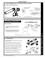
IMPORTANT. The boiler MUST be installed in a vertical position

Dimension X - Wall thickness.

Dimension L - Wall thickness plus boiler spacing.

Dimension S - Stand-off frame depth = 33mm

12 DETERMINING THE FLUE LENGTH AND FLUE PACKS REQUIRED

Notes.

1. The flue duct MUST be inclined at 1.5 degrees

to the horizontal to allow condensate to drain
back into the boiler and out through the
condensate drain.

2. If the boiler is to be installed with upward piping

routed behind the boiler then the optional
stand-off kit should be used. Care must be
taken when cutting the ducts and marking the
wall to suit this condition.

Total Flue length dimension

Flue

Rear flue

Side flue

Extra packs

dim. X+160

 dim. L+195

required

Up to

650 mm

Up to

650 mm

none

Up to 1600 mm

Up to 1600 mm

Pack D - 1 off

Up to 2550 mm

Up to 2550 mm

Pack D - 2 off

Up to 3500 mm

Up to 3500 mm

Pack D - 3 off

Up to 4450 mm

Up to 4450 mm

Pack D - 4 off

Up to 5400 mm

Up to 5400 mm

Pack D - 5 off

Up to 6000 mm

Up to 6000 mm

Pack D - 6 off

INST

ALLA

TION

Содержание isar m30100

Страница 1: ......

Страница 2: ...Key to symbols GB United Kingdom IE Ireland Countries of destination PMS Maximum operating pressure of water C13 C33 C53 A room sealed appliance designed for connection via ducts to a horizontal or vertical terminal which admits fresh air to the burner and discharges the products of combustion to the outside through orifices which in this case are concentric The fan is up stream of the combustion ...

Страница 3: ...trol to heating 24 Time and temperature control to hot water 24 Heating zone valves n a TRV s 8 Auto bypass 8 Boiler interlock 8 For all boilers Flushing to BS 7593 10 Inhibitor 10 Central heating mode Heat input to be calculated For assistance see Technical Helpline on the back page Page Burner operating pressure measure and record Central heating flow temp measure and record Central heating retu...

Страница 4: ...m the boiler is routed downwards as standard but may be routed upwards behind the boiler using the stand off frame supplied in a separate kit OPERATION With no demand for CH the boiler fires only when DHW is drawn off or periodically for a few seconds without any DHW draw off in order to maintain the DHW calorifier in a heated condition When there is a demand for CH the heating system is supplied ...

Страница 5: ...ry or CFCs are included in any part of the boiler or its manufacture LOCATION OF BOILER The boiler must be installed on a flat and vertical wall capable of adequately supporting the weight of the boiler and any ancillary equipment The boiler may be fitted on a combustible wall and insulation between the wall and the boiler is not necessary unless required by the local authority For electrical safe...

Страница 6: ...is 5mm 1 4 from the cupboard door but 450mm 17 3 4 overall clearance is still required with the cupboard door open to allow for servicing Bottom clearance Bottom clearance after installation can be reduced to 5mm However 100mm must be available for servicing wall thicknesses do not exceed 600mm 24 Where the space into which the boiler is going to be installed is less than the length of flue requir...

Страница 7: ...RCULATION SYSTEM IMPORTANT A minimum length of 1 metre of copper pipe MUST be fitted to both flow and return connections from the boiler before connection to any plastic piping The central heating system should be in accordance with BS 6798 and in addition for smallbore and microbore systems BS 5449 WATER TREATMENT see Frame 6 GAS SUPPLY The local gas supplier should be consulted at the installati...

Страница 8: ...dequate flow when all TRVs are closed For further information refer to the Good Practice Guide 143 a publication of the Energy Efficiency Office available from the Building Research Establishment Garston Watford WD2 7JR Tel 44 0 1923 664258 ELECTRICAL SUPPLY WARNING The appliance MUST be efficiently earthed Wiring external to the appliance MUST be in accordance with the current I E E BS 7671 Wirin...

Страница 9: ...supplied from a service pipe under mains pressure Where the mains pressure is excessive a pressure reducing valve must be used to facilitate filling When installing the filling device it must be connected as shown below to fully comply with the water regulations This may involve the fitting of an additional WRAS approved isolator valve to the mains supply i Thoroughly flush out the whole system wi...

Страница 10: ...heating system 3 In hard water areas treatment to prevent limescale may be necessary however the use of artificially softened water is NOT permitted 4 Under no circumstances should the boiler be fired before the system has been thoroughly flushed Domestic Hot Water In hard water areas where main water can exceed 200ppm Total Hardness as defined by BS 7593 1993 Table 2 a scale reducing device shoul...

Страница 11: ...llation and Servicing 8 BOILER ASSEMBLY Exploded View 8 5 44 53 14 13 15 62 59 18 64 4 2 63 1 69 75 35 36 66 70 32 23 67 23 68 24 71 17 26 25 3 19 57 60 6 11 12 39 Ecl 6065 21 16 61 57 60 51 65 10 9 20 22 Data badge INSTALLATION ...

Страница 12: ...ff Water treatment warning label Turret clamp M5 x 10 pozi Hex screw S Trap hose Pack A Contents Hardware Pack and fittings These Installation Servicing Instructions The User s Instructions The user Control display unit Benchmark log book 2 year guarantee form Pack B Contents Flue turret Flue terminal Flue support cutting aid Ecl 2354 Flue terminal Flue turret Safety drain pipe nut and olive CH Fl...

Страница 13: ...oroughly before unpacking the product 5 When ready for installation lift off the cardboard carton 10 PACKAGING REMOVAL Ecl 2356 11 BOTTOM PANEL AND FRONT PANEL REMOVAL 1 Remove the 2 screws from the underside of the boiler 2 Pull the panel forward at the bottom and lift to disengage it from the top lugs 3 Remove the screws from the underside of the boiler 4 Pull the RHS of the panel down slide it ...

Страница 14: ...he horizontal to allow condensate to drain back into the boiler and out through the condensate drain 2 If the boiler is to be installed with upward piping routed behind the boiler then the optional stand off kit should be used Care must be taken when cutting the ducts and marking the wall to suit this condition Total Flue length dimension Flue Rear flue Side flue Extra packs dim X 160 dim L 195 re...

Страница 15: ...osition of the flue duct hole see diagram below and template Note Mark the centre of the hole as well as the circumference 5 Remove the template from the wall 14 WALL MOUNTING TEMPLATE 13 FLUE ASSEMBLY Exploded View An optional flue duct extension kit is required for wall thicknesses greater than Side 455mm 18 Rear 490mm 19 1 4 Rear flue arrangement shown Ecl 2360 V A A B B B Extended centre line ...

Страница 16: ...ssential add 33mm to X the measured wall thickness when marking the flue this will allow for the fitted frame 1 Measure and note wall thickness X Refer to Frame 12 2 Add 90mm 3 1 2 to dimension X and measuring from the ring cut the outer tube only 3 To ensure the tube is cut square mark the flue all the way round 4 Cut the inner tube to a length 20mm 3 4 longer to aid engagement using the cardboar...

Страница 17: ...hs together 5 Repeat steps 1 4 if a second flue extension is required 6 Measure and mark the flue length required onto the flue measuring from the ring near the terminal 7 To ensure a square cut mark the flue all the way round 8 Cut to length using the cardboard support aid 9 Remove the cardboard and deburr the metal edges 20 FITTING THE KIT 18 FLUE EXTENSION DUCTS For flue lengths greater than 65...

Страница 18: ...f frame To allow pipework to be taken upwards Insert wall plugs Put the screws into the wall plugs and leave 10mm proud Hang the stand off frame onto the screws and tighten up Fasten the piping frame to the stand off frame with the 6mm screws provided Locate the support bracket on the piping frame Note If the clearances above and below the boiler are less than the length of the pipes it will be ne...

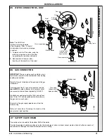
Страница 19: ...pack 7 Plug the user control display unit pack A into the control box Refer to Frame 65 8 Screw the user control into position 23 CONNECTING THE FLUE TO THE BOILER Note Before fitting the flue turret fill the condensate trap within the boiler by pouring a cupful of water into the flue outlet A Take care to ensure that the water is only poured into the flue outlet and does not spill into the boiler...

Страница 20: ...onnect the boiler flow and return pipes to 28mm system pipework 2 Do not subject any of the isolating valves to heat as the seals may be damaged C H FLOW C H RETURN Ecl 2396 22mm copper pipe Isolating valve shown in the open position Piping frame Drain point 22mm copper pipe Isolating valve shown in the open position Pressure gauge Condensate drain pipe located here ...

Страница 21: ...lary connections Refer to Frame 2 for details of the position of the gas connection The principle of the 1 1 gas valve ensures that the isar m30100 is able to deliver its full output at inlet pressures well below those required by BS 6891 A boiler gas supply pipe length of 20m and not less than 15mm O D can be connected to the boiler via the gas service cock union Ensure that the gas supply pipe d...

Страница 22: ...in the condensate drain system must be made of plastic No other materials may be used The drain outlet on the boiler is standard 21 5mm overflow pipe This size must not be reduced in any part of its length 29 FILLING Central Heating 1 Remove the boiler front and sealing panels Refer to Frames 42 43 2 Swing the control box down into the servicing position Refer to Frame 44 3 Ensure that the CH isol...

Страница 23: ... E E BS 7671 Wiring Regulations and any local regulations 1 Route the mains cable into the bottom rear centre of the boiler 2 Wire the permanent live supply into the 5 way remote plug terminals L3 N IMPORTANT A permanent live is ESSENTIAL in order for the advanced diagnostic controls to function correctly 31 INTERNAL WIRING 3 Wire any switched live supply into L2 or connect L1 and L2 via external ...

Страница 24: ... OFF and all the other controls MUST be left in the running position The frost thermostat should be sited in a cold place but where it can sense heat from the system Note If the boiler is installed in a garage it may be necessary to fit a pipe thermostat preferably on the return pipework Wiring should be as shown with minimal disturbance to other wiring of the programmer Designation of the termina...

Страница 25: ...ol thermistor flow Gas valve PUMP Control thermistor return DHW Thermistor User control and display ON OFF Switch Service connection Mains supply 230V 50Hz Permanent black link Fan bk y Chassis earth y g Ecl 2439 Fused at 3 15ATL r r b b br Diverter valve Filter Control PCB PHC 033 33 PICTORIAL WIRING DIAGRAM LEGEND b blue bk black br brown gy grey or orange pk pink r red v violet w white y yellow...

Страница 26: ...lation including the meter should be inspected and tested for soundness and purged in accordance with the recommendations of BS 6891 In IE refer to I S 813 2002 2 Purge air from the gas installation by the approved methods only 35 COMMISSIONING AND TESTING 3 2 1 bk or or Diverter valve gy v r v v v v Pump pk br y g b y g DC gas valve b r br Mains switch DC Fan r bk y pk b Flame detection electrode...

Страница 27: ...ld now be illuminated The boiler control should The display The user control has one neon and one display to inform the user about the status The display will show the status of the boiler The neon will show the status of the flame If no flame is detected the neon is blinking When the flame is detected the neon will be lit permanently Below is a list with display function in normal operation Stand...

Страница 28: ... 18 Set the boiler on off switch A to OFF 19 Swing the control box into the servicing position Refer to Frame 44 20 Remove the pressure gauge and tube Tighten the sealing screw in the pressure test point Ensure a gas tight seal is made 21 Swing the control box back into its working position and secure Reconnect the ignition lead 22 Refit the user control 23 Refit the boiler front and bottom panels...

Страница 29: ...t mode Emphasise that if a fault is indicated the boiler should be turned off and a CORGI registered installer consulted In IE contact a Competent Person 6 Explain and demonstrate the function of time and temperature controls radiator valves etc for the economic use of the system WATER TEMPERATURES Temperatures can be selected via the CH and DHW thermostats 39 GENERAL CHECKS continued CH DHW CONT ...

Страница 30: ...If not proceed to Step 5 but see note above 4 Clean the main burner 5 Clean the heat exchanger 6 Check the condition of the combustion chamber insulation Any cracked damaged pieces should be replaced 7 Check the main injector for blockage or damage 8 Wherever possible remove and clean the condensate S trap refer to Frame 47 and check the drain for blockage 9 Check that the flue terminal is unobstr...

Страница 31: ... of the boiler 2 Pull the panel forward at the bottom and lift to disengage it from the top lugs Ecl 2442 1 1 To remove the sealing panel remove the 4 screws 2 Remove the panel 3 To remove the bottom panel remove the 2 screws 4 Pull the right hand side of the panel down Slide it to the right and withdraw Ecl 2443 3 1 Flue gas sampling point Ecl 2443 SERVICING ...

Страница 32: ...ntrol 2 Unplug the low voltage electrical lead from the back of the user control 3 Unplug the igntion lead from the bottom of the control box 4 Turn the clamp swing the control box down and pull slightly forward Control box User control Ecl 2398 1 3 2 Swing control panel down and forward into service position Clamp 4 Ecl 2399 SERVICING ...

Страница 33: ...s face as this may cause damage to the ceramic 3 Brush off any deposits that may be on the ceramic with a SOFT brush 4 Inspect the sealing gasket around the burner and combustion chamber insulation for any signs of damage Replace as necessary Note Take care not to disturb the detection earth probe at the rear of the combustion chamber 1 Disconnect the electrical leads from the fan 2 Undo the gas p...

Страница 34: ...d remove any loose deposits from the sump 5 Inspect the ignition and detection electrodes Ensure that they are clean and in good condition replace if necessary 6 Check that the ignition and detection gaps are correct Refer to Frames 56 57 7 Check the condition of the combustion chamber insulation Any cracked damaged pieces should be replaced Note Take care not to disturb the detection earth probe ...

Страница 35: ...3 Disconnect the electrical leads from the fan 4 Undo the gas pipe union connection to the injector housing 5 Remove the screw retaining the fan mounting bracket 6 Remove the fan and venturi assembly 7 Unscrew the 3 screws and remove the venturi assembly noting the orientation of the venturi in relation to the fan body 8 Transfer the venturi assembly to the new fan replacing the gasket if evidence...

Страница 36: ...ove the screw retaining the fan mounting bracket 6 Remove the fan and venturi assembly 7 Remove the 2 injector housing screws 8 Withdraw the injector housing 9 Fit the new injector housing complete with injector 10 Reassemble in reverse order ensuring that the new gas seal supplied is located correctly in the injector housing 11 Check operation of the boiler Refer to Frame 50 Mounting bracket 7 Ec...

Страница 37: ... 5 Remove the screw holding the ignition electrode to the combustion chamber 6 Remove the earth lead from the ignition electrode 7 Remove the electrode taking care not to dislodge the grommet from the casing 8 Fit the new ignition electrode using the new gasket supplied Check dimensions as shown 9 Reassemble in reverse order 10 Check the operation of the boiler Refer to Frame 50 5 Remove the screw...

Страница 38: ...h the spare part 7 Remove the detection earth probe 8 Damp down the combustion chamber area containing the insulation boards 9 Remove the split pin and washer from the RHS of the combustion chamber 10 Remove the insulation boards The replacement boards are supplied in a plastic bag This bag should be retained and the discarded boards should now be placed into it 11 Sweep any dampened particles and...

Страница 39: ...e 9 Transfer the mounting bracket and gas inlet pipe to the new gas control valve 10 Fit the new gas control valve ensuring that any seals showing damage or deterioration are replaced Reassemble in reverse order 11 Ensure the sensing tube is correctly replaced and not kinked or blocked in any way 12 Check operation of the boiler Refer to Frame 50 60 DIVERTER VALVE ACTUATOR REPLACEMENT 1 Refer to F...

Страница 40: ...lt 5 62 DHW THERMISTOR REPLACEMENT 1 Refer to Frame 50 2 Remove the casing front bottom panel Refer to Frames 42 43 3 Remove the 4 screws securing the support plate and withdraw the plate Note The M4 screws fit the casing and the self tapping screws fit the plastic pump and valve housings 4 Withdraw the securing pin 5 Disconnect the electrical lead 6 Ease out the sensor and discard 7 Fit the new s...

Страница 41: ... voltage lead from the control box and remove the control Refer to diagram A 5 Return the control box to the working position and secure with the clamp Unscrew the mounting bracket screws to remove the bracket Refer to diagram B 6 Release the clamp and carefully remove the control box from the hinge arms Refer to diagram C 7 Unplug all the electrical wiring from the control box and remove 8 Transf...

Страница 42: ...in reverse order 6 Check operation of the boiler Refer to Frame 50 65 USER CONTROL REPLACEMENT 66 PRESSURE GAUGE REPLACEMENT 1 Refer to Frame 50 2 Drain the boiler Refer to Frame 69 3 Unscrew the pressure gauge and discard 4 Fit the new pressure gauge using a suitable jointing compound 5 Refill the boiler Refer to Frame 29 6 Check operation of the boiler Refer to Frame 50 2041 Pressure gauge Flow ...

Страница 43: ... O ring provided and reassemble in reverse order Note In the event that the extension pipe is removed at the same time as the air vent remove it from the air vent and refit it into the heat exchanger before fitting the new air vent ensuring that its O ring seal is in place IMPORTANT Ensure that the vent cap A is loose 6 Refill the boiler Refer to Frame 29 7 Check the operation of the boiler Refer ...

Страница 44: ... 3 Drain the boiler Refer to Frame 69 4 Remove the 4 screws retaining the rear support plate and withdraw the plate Refer to Frame 67 Note The M4 screws fit the casing and the self tapping screws fit the plastic pump and valve housings 5 Remove the valve actuator head Refer to Frame 60 6 Remove the 4 Allen screws and remove the valve mechanism 7 Fit the new valve mechanism and gasket ensuring corr...

Страница 45: ...r to Frame 29 11 Check operation of the boiler Refer to Frame 50 71 DHW PLATE HEAT EXCHANGER REPLACEMENT 1 Refer to Frame 50 2 Remove the casing front bottom panel Refer to Frames 42 43 3 Drain the boiler Refer to Frame 69 4 Remove the 4 screws securing the rear support plate and withdraw the plate Refer to Frame 67 Note The M4 screws fit the casing and the self tapping screws fit the plastic pump...

Страница 46: ...e thermistor 15 Undo the 2 M5 x 10 flue spring clip retaining bracket screws and remove the bracket 16 Remove the flue casting 73 HEAT ENGINE REPLACEMENT 17 Remove the edge clip securing the flue thermistor wiring 18 Remove the blind grommet to gain access to the return pipe securing bracket 19 Unscrew the M5 screw and remove the return pipe securing bracket by sliding forwards 20 Remove the overh...

Страница 47: ...fer to Frame 69 3 Unscrew all the gas and water connection unions on the boiler side of the valves 4 Remove the screw from the turret clamp and remove 5 Remove the turret 6 Lift the complete boiler from the wall mounting frame and place on a flat surface face down to expose the expansion vessel 7 Unscrew the union nut on the vessel water connection pipe 8 Unscrew the 2 screws from the securing cla...

Страница 48: ... FRAME 78 ALTERNATING L A GO TO FRAME 79 ALTERNATING L 8 GO TO FRAME 80 ALTERNATING H 1 GO TO FRAME 81 ALTERNATING H 2 GO TO FRAME 82 ALTERNATING H 3 GO TO FRAME 83 ALTERNATING H 4 GO TO FRAME 84 ALTERNATING H F GO TO FRAME 85 In order to assist fault finding the boiler has an LED diagnostic display The key to the display codes is as follows ALTERNATING H n GO TO FRAME 86 ALTERNATING H E GO TO FRA...

Страница 49: ...et button is pressed does the boiler ignite for a short time then extinguish Is 200V DC supply available at the gas valve see Note NO YES YES Is gas pressure available at the boiler inlet Replace PCB Check gas supply and rectify fault Replace ignition electrode and associated harness as necessary NO Replace gas valve YES NO NO 78 L E or H E PCB ERROR Internal fault within the PCB Replace PCB Note ...

Страница 50: ...em filled with water and all isolation valves open OK NO YES NO Replace overheat thermostat 80 L 8 FAN ERROR Is nominal 330 V DC present across red and blue at the fan connector as reset button is pressed Replace fan YES NO Replace harness 81 H 1 CONTROL THERMISTOR FLOW ERROR YES Is there continuity between the PCB and the thermistor Check resistance using a suitable multimeter connected across th...

Страница 51: ...uity between the PCB and the thermistor Remove the boiler DHW thermistor from the plate heat exchanger and disconnect thermistor wires Are the thermistor values correct Replace the thermistor NO NO YES Replace PCB Check and replace wiring as necessary Check resistance using a suitable multimeter connected across the thermistor s terminal pins At 25 o C expect 9 700 10 300 Ohms At 60 o C expect 2 4...

Страница 52: ...or damage in the flueways Clean or replace as necessary Replace thermistor NO 86 H n PHASE REVERSAL ERROR Check wiring to the boiler for reversed live and neutral YES NO YES NO 85 H F FLAME DETECTION ERROR Replace flame detection electrode Is there continuity between the 2 terminal pins NO YES Remove flame detection electrode terminal from PCB Replace PCB Check resistance using a suitable multimet...

Страница 53: ...916 23 E67 501 Control thermistor flow return 2 170 917 24 E67 502 Overheat thermostat 1 170 918 25 E69 291 Ignition electrode and gasket 1 170 985 26 E67 504 Flame detection electrode and gasket 1 170 920 32 E67 511 Condensate S trap 1 170 926 35 E69 394 User control display unit 1 170 993 36 E85 103 PCB primary controls includes plastic housing 1 172 490 37 E67 519 Fuse PCB 3 15A L250V 1 170 931...

Страница 54: ...54 SHORT LIST OF PARTS isar Installation and Servicing 87 SHORT LIST Ecl 2408 45 52 53 19 25 22 14 11 16 17 23 24 62 32 71 65 69 64 61 67 66 35 39 37 26 12 36 ...

Страница 55: ...ith screws 4 Bottom panel with screws Ecl 2101 1 4 2 89 CONTROLS ASSEMBLY 33 Controls assy with screws 34 Controls hinge bracket 35 User controls without item 38 36 PCB primary controls 38 User controls housing 39 Mains switch 54 Jumper link not shown 90 BURNER ASSEMBLY 11 Burner assembly with screws and gasket Ecl 2552 36 34 39 38 35 ...

Страница 56: ...d to vary specification without notice The Ideal Boilers Technical Training Centre offers a series of first class training courses for domestic commercial and industrial heating installers engineers and system specifiers For details of courses please ring 01482 498 432 CERTIFIED PRODUCT Manufactured under a BS EN ISO 9001 1994 Quality System accepted by BSI The code of practice for the installatio...

Отзывы: