A S S E M B L I N G G U I D E L I N E
M A _ C A L E O S Y S T E M _ E N _ 2 1 A
Rev
. 21A
AKE GmbH
page 4 of 12
2
Assembling instructions “Caleo system”
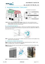
Example for “Caleo system”:
NOTE:
When installing
2 identical units together
(Caleo Cold -> Caleo Cold), the side wall
glasses between the units can be removed. Depending on the model type (cooling, neutral,
heating), different assembly aids can be used
2.1
Connection of the devices
All Caleo units are equipped with a base frame. A blind rivet nut is installed in the left front base frame
tube on each unit. Connect two units standing next to each other with a screw (M8x20mm; DIN912) to
the provided blind rivet nut.
NOTE:
The base frame cover may have to be drilled. A back panel connector must be attached to the
upper corners of each back wall.
2.2
Back-to-back / Side-by-side installation
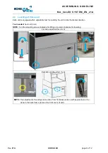
Step 1:
All Units must be levelled and adjusted on same height before build-
up of “system” can be
done. For installation steps / instructions see
chapter 2.3
.
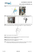
Step 2:
Attach the back panel connection plates to both units as shown and fix them with M4 screws
or blind rivets Ø4mm.
NOTE:
Pay attention to the defined installation position of each panel.


