ICT PRT-IPIC-POE Скачать руководство пользователя страница 37

Trigger a Protege Input with Your Phone

The following steps outline how to set up a code which can be entered during a VoIP call from an IP phone to the
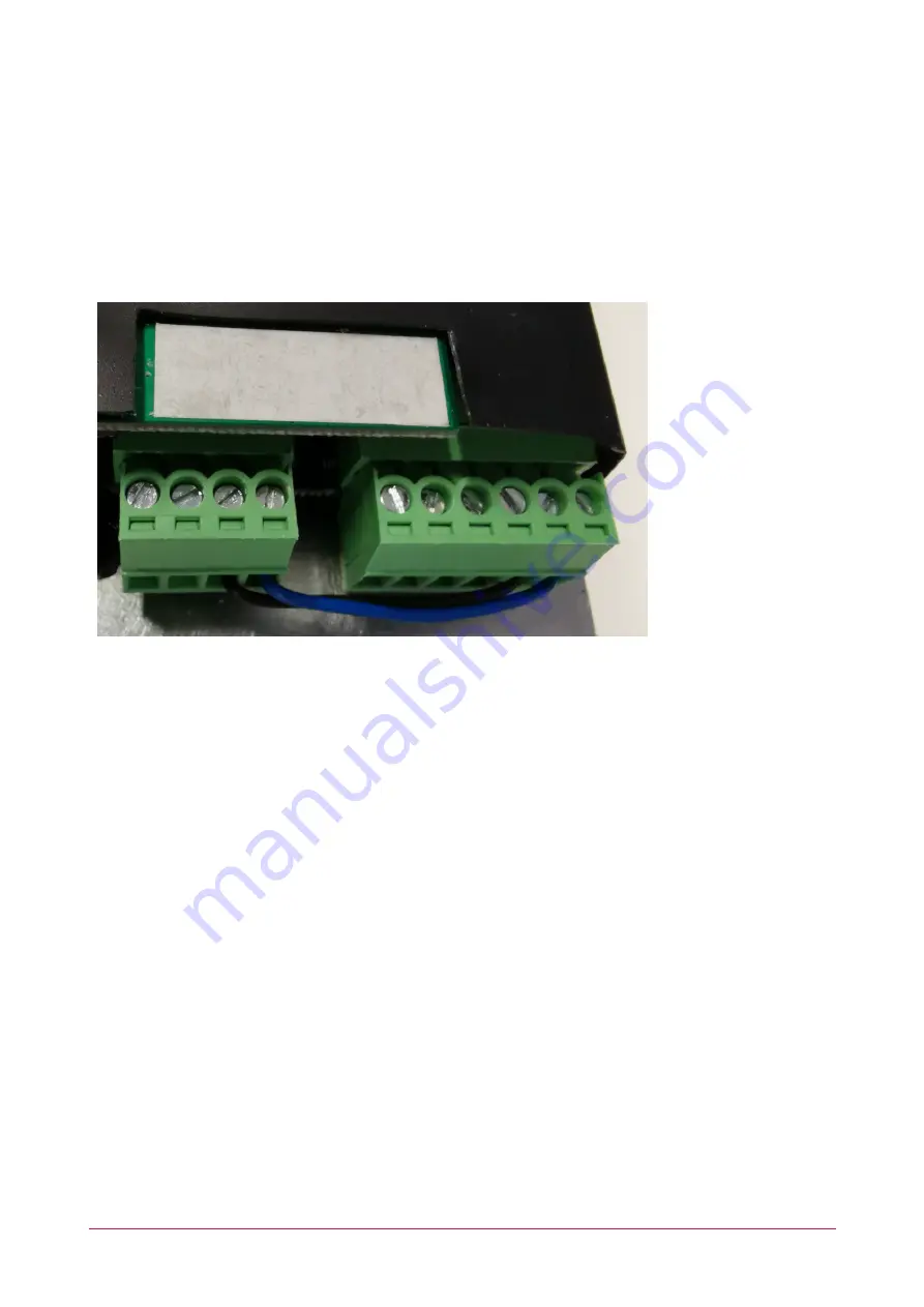
intercom, enabling the user to remotely trigger a Protege input.

To enable this functionality the intercom unit's connection terminals need to be wired as below, with the input port
contacts connected to the output port contacts:

The GND1 terminal connected to the COM1 (Common contact) terminal.

The IN1 (Input 1) terminal connected to the NO1: (Normally open contact) terminal.

The intercom then needs to be configured to respond to the Remote DTMF Trigger.

1.

From the intercom web interface, navigate to the

Security Settings

menu.

2.

In the

Input Settings

section, check

Input Detect

.

-

Set the

Trigger Mode

to

High Level Trigger (Disconnect Trigger)

.

-

Check

Alert message send to server

.

3.

In the

Output Settings

section, check

Output Response

.

-

Set the

Output Level

to

High Level (NC:closed)

.

-

Set the

Output Duration

to 1 second.

4.

In the

Alert Trigger Setting | Output

section, check

Remote DTMF Trigger

.

-

Disable the

Input Trigger

.

5.

Set the

Trigger Code

to the code that will be entered to trigger the input.

(

valid characters for trigger code entry are: 0-9, * and #

)

6.

Set the

Reset Mode

to

By Duration

.

7.

To play a tone when the input is triggered, in the

Alert Trigger Setting | Ring

section, set

Remote

DTMF Trigger

to

Default

.

-

Set the

Alarm Ring Duration

to the desired duration.

8.

Click

Apply

.

PRT-IPIC-POE | Protege Vandal Resistant VoIP Intercom | Installation Manual

37

Содержание PRT-IPIC-POE

Страница 1: ...PRT IPIC POE Protege Vandal Resistant VoIP Intercom Installation Manual...

Страница 2: ...echanical for any purpose without the express written permission of Integrated Control Technology Limited Designed and manufactured by Integrated Control Technology Limited Protege and the Protege Log...

Страница 3: ...all Mounting Installation 10 Hardware Configuration 12 Power on Sequence 12 Finding the Intercom on the Network 12 Defaulting the Intercom 13 Programming the Intercom 14 Intercom Web Interface 14 Init...

Страница 4: ...28 Security Settings 29 Function Key 31 Main Secondary Operation 31 Day Night Operation 31 Standalone Functionality 33 Unlock a Door with Your Phone 33 Unlock a Door with REX 34 Configuring the Tamper...

Страница 5: ...ealand and Australia 41 European Standards 42 FCC Compliance Statements 44 Industry Canada Statement 45 Disclaimer and Warranty 46 PRT IPIC POE Protege Vandal Resistant VoIP Intercom Installation Manu...

Страница 6: ...mber or call another VoIP device Programmable auto answer Interact with the controller to allow control of devices such as lights and doors Allows local door control 2 onboard inputs 2 onboard Form C...

Страница 7: ...commended for multiple intercom installations or simply connect the intercom and the controller to the building s existing network When installing an ethernet connection the intercom should be interfa...

Страница 8: ...ses with the option to use static addressing RTP SRTP Audio Encodings G 711U PCMU G 711A PCMA G 722 G 723 1 G 726 32 G 729AB SIP Servers The intercom supports SIP servers that comply with SIP protocol...

Страница 9: ...Input for configuration details see page 35 Onboard Outputs There are two onboard Form C relay outputs These standalone outputs can be used to control devices such as door locks or lights directly fro...

Страница 10: ...he intercom will be located 2 Drill 4 holes over the marks provided on the template A drill hole depth of 50mm is recommended 3 Remove the template and insert the screw anchors into the holes Mounting...

Страница 11: ...3 seconds to obtain the IP address of the intercom unit Do Not proceed until the electric checks are confirmed Completion Attach the front panel carefully into the back panel and replace the 4 screws...

Страница 12: ...unknown 1 Ensure the intercom is powered on 2 Remove the screws using the hex key provided and remove the front panel 3 Lift the main body of the intercom out of the enclosure 4 Locate and press the...

Страница 13: ...static IP address in the 192 168 10 xxx range xxx can be from 2 254 3 Remove the power to the intercom 4 Put the intercom into Update Mode by holding down the and buttons then connecting power After 5...

Страница 14: ...ported by ICT or the integration and as such those options are not documented here Accessing the Web Interface 1 Open a web browser and enter the default IP address of the intercom 192 168 1 128 2 Whe...

Страница 15: ...er IP or URL usually the same as the SIP Registrar Server SIP Proxy Server Port Proxy server port Usually 5060 3 Click Apply If the SIP account is correctly configured the Line Status should display A...

Страница 16: ...SIP Accounts Displays the phone numbers and registration status for the SIP Lines if configured System Account Enables management of users including adding and removing users and changing passwords a...

Страница 17: ...cted user 3 New Password Enter the new password to assign for the user to log in 4 Confirm Password Repeat the new password 5 Privilege Set the privilege level for the selected user 6 Click Apply to a...

Страница 18: ...com inoperable Version 2 6 0 6680 represents a significant change in the firmware file format and upgrade process In order to transition from the older format to the newer bin file firmwares a middle...

Страница 19: ...is feature is not supported Reboot Some configuration modifications require a system reboot to take effect Click the Reboot button to perform an immediate reboot on the device Save the configuration b...

Страница 20: ...parameters are provided by the network administrator DHCP Network parameters are provided automatically by a DHCP server PPPoE This feature is not supported Note Any changes made on this page require...

Страница 21: ...be downloaded to the intercom before using HTTPS HTTPS Certification File Click Select to browse and select the required certification file Click Upload to load the file to the device Click Delete to...

Страница 22: ...Password SIP registration password Activate This option must be selected to activate the line SIP Proxy Server Address Proxy server IP or URL usually the same as the SIP Registrar Server SIP Proxy Ser...

Страница 23: ...h Registration Expiration The SIP expiration frequency Use VPN Set the line to use a restricted VPN Use STUN Set the line to use STUN for NAT traversal Convert URI Convert non alphanumeric characters...

Страница 24: ...ings Local SIP Port The port the intercom uses to connect to the SIP server The default Local Port is 5060 This may be adjusted if required by the network administrator Registration Failure Retry Inte...

Страница 25: ...Line Action Plan This feature is not supported PRT IPIC POE Protege Vandal Resistant VoIP Intercom Installation Manual 25...

Страница 26: ...Description The broadcast identification of the intercom Enable DND Do Not Disturb Prevents incoming calls according to the DND Mode Outgoing calls will not be affected HangUp Delay The duration in se...

Страница 27: ...feature is not supported Intercom Settings MCAST This feature is not supported Intercom Settings Action URL This feature is not supported Intercom Settings Time Date There are two methods for setting...

Страница 28: ...led To manually set the time select the Year Month Date Hour and Minutes then click Apply Intercom Settings Time Plan This feature is not supported Intercom Settings Trusted Certificates This feature...

Страница 29: ...he alert triggers that will activate the onboard output Input Trigger Whenever the input configuration meets the trigger condition the output will be triggered Reset Mode The triggered output can be r...

Страница 30: ...r Tamper Alarm Settings Tamper Alarm Select to enable the tamper alarm Alarm Command Message sent as a SIP message when a tamper alarm is triggered Reset Command Message which should be received from...

Страница 31: ...d the call button can be used to end a call Hot Key Dial Mode Select When set to Main Secondary Number 2 will be called when the first number is not answered The Call Switched Time defines the delay i...

Страница 32: ...during night hours 4 Select the corresponding Line Line 1 or Line 2 for the SIP account 5 From the Subtype list select Speed Dial Advanced Settings 1 Hot Key Dial Mode Select set to Day Night and cli...

Страница 33: ...closed when activated When set to Low Level NO open the normally open contact will be closed when deactivated and open when activated 4 In the Alert Trigger Setting Output section check Remote DTMF Tr...

Страница 34: ...n activated When set to Low Level NO open the normally open contact will be closed when deactivated and open when activated 6 Set the Output Duration to the duration in seconds the door should unlock...

Страница 35: ...ttings menu 4 In the Server Settings section set the Server Address to the IP address of the Protege controller 5 Click Apply to update Configuring the Onboard Input as a Protege Input The intercom s...

Страница 36: ...ng 11 In the pop up window locate the new Keypad record identified by the Address assigned above 12 Check that the Registered and Online columns display True If so the intercom is successfully connect...

Страница 37: ...to the Security Settings menu 2 In the Input Settings section check Input Detect Set the Trigger Mode to High Level Trigger Disconnect Trigger Check Alert message send to server 3 In the Output Setti...

Страница 38: ...Mechanical Diagram PRT IPIC POE Protege Vandal Resistant VoIP Intercom Installation Manual 38...

Страница 39: ...Wall Mounting Template PRT IPIC POE Protege Vandal Resistant VoIP Intercom Installation Manual 39...

Страница 40: ...ut One 3 5mm terminal block Short circuit input Two 3 5mm terminal block Short circuit output Two Form C relays 3 5mm terminal block 24V DC 1A WAN port 10 100BASE TX s Auto MDIX RJ 45 Cables CAT5 or b...

Страница 41: ...a General Product Statement The RCM compliance label indicates that the supplier of the device asserts that it complies with all applicable standards PRT IPIC POE Protege Vandal Resistant VoIP Interco...

Страница 42: ...ste handling Please contact your local authority for further details of your nearest designated collection point Penalties may be applicable for incorrect disposal of this waste in accordance with you...

Страница 43: ...0131 1 Single Button Setting should not be selected To comply with EN 50131 1 only one battery can be connected and monitored per system If more capacity is required a single larger battery must be us...

Страница 44: ...his device may not cause harmful interference This device must accept any interference received including interference that may cause undesired operation NOTE THE GRANTEE IS NOT RESPONSIBLE FOR ANY CH...

Страница 45: ...ICES 003 This is a Class A digital device that meets all requirements of the Canadian Interference Causing Equipment Regulations CAN ICES 3 A NMB 3 A PRT IPIC POE Protege Vandal Resistant VoIP Interc...

Страница 46: ...l be liable under any circumstances to any party in respect of decisions or actions they may make as a result of using this information In accordance with the ICT policy of enhanced development design...

Страница 47: ...aimer Whilst every effort has been made to ensure accuracy in the representation of this product neither Integrated Control Technology Ltd nor its employees shall be liable under any circumstances to...

Отзывы: