
Control and maintenance
8
Service Unit iMAT 33
Pos : 27 /Beko T ec hnis che D okumentati on/Sic her hei t/Hinweis Vorschriften Wer kzeug R einigung Kondensat Entsorgung @ 0\mod_1233239666823_15098.doc x @ 15301 @ @ 1
Note
It is imperative to observe all hazard statements and warnings listed here.
Please also observe all regulations and notes regarding industrial safety and fire prevention at the place of
installation.
As a matter of principle, only use suitable and appropriate tools and materials in a proper condition.
Do not use aggressive cleaners and improper devices such as high-pressure cleaners.
Please note that condensates may contain aggressive or harmful components. Therefore, skin contact
should be avoided.
Condensate is subject to mandatory waste disposal. As such, it must be collected in suitable containers, and
disposed of or processed properly.
Pos : 28 /Beko T ec hnis che D okumentati on/Wartung/BEKOM AT/Wartung BM 33U Ser vice-U nit ( ohne War tungsempfehl ung) @ 6\mod_1378723767212_15098.doc x @ 33567 @ @ 1
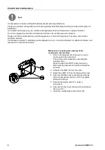
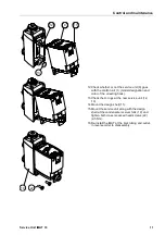
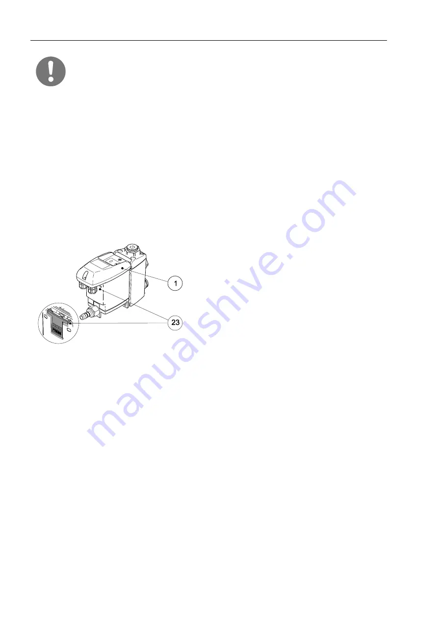
Maintenance including the cleaning of the
condensate receiver tank:
1.
Prior to the replacement of the service unit, a
reset needs to be carried out.
The control unit is released by actuating the
arresting hook.
When removed, the TEST button below the
LED must be pressed and held for at least five
seconds.
2.
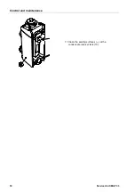
Unfasten the iMAT 33
from the outlet.
3. Detach the iMAT 33 from the tubing at the inlet.
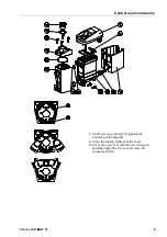
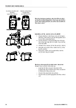
4. Unscrew both M6 cross recessed head screws
(22) and remove the service unit (9) by slightly
pulling and lifting it.
5. Remove the design shell (11) using a
screwdriver.
6. Unscrew the four cover screws (16) and remove
the cover (17).
7.
Clean the condensate receiver tank (19).
Содержание Service Unit iMAT 33
Страница 2: ...2 Service Unit iMAT 33...