ICP DAS USA DNP-211 Скачать руководство пользователя страница 4


Version 1.0.1              

DNP-211 User Manual

               2022/06/01 

1.


  Introduction 

1.1.


  DNP3 Introduction 

DNP3 (Distributed Network Protocol 3) is a communication protocol used 
between automation components. The protocol is formulated with 
reference to IEC 870-5. The purpose is to unify the communication 
method of SCADA so that SCADA can use the DNP3 protocol to 
communicate with master stations, remote terminal units (RTUs), 
intelligent electronic devices (IEDs), etc., and are mainly used in  utilities 
such as electric and water companies. 
The DNP3 protocol has certain  of reliability and allows  reliable 
communications in the adverse environments that electric utility 
automation systems are subjected to  being specifically designed to 
overcome distortion induced by electromagnetic interference (EMI), 
aging components, and poor transmission media. A large number of CRC 
check codes are used in the protocol to ensure the accuracy of data. It is 
suitable for high security, Data communication field of medium speed and 
medium amount of data. 
 

1.2.


  Modbus TCP Introduction 

Modbus TCP is a variant of the Modbus family of simple, vendor-neutral 
communication protocols intended for supervision and control of 
automation equipment. Specifically, it covers the use of Modbus 
messaging in an “Intranet” or “Internet” environment using the 
TCP/IP  protocols. The most common use of the protocols at this time is 
for Ethernet attachment of PLC’s, I/O modules, and gateways to other 
simple field buses or I/O networks. 
 

Содержание DNP-211

Страница 1: ...User Manual Version 1 0 1 Jun 2022 DNP 211 DNP3 Master to Modbus TCP Server Gateway...

Страница 2: ...ge this manual at any time without notice The information furnished by ICP DAS is believed to be accurate and reliable However no responsibility is assumed by ICP DAS for its use nor for any infringem...

Страница 3: ...ware 7 2 1 Dimensions 7 2 2 Appearance 8 2 3 LED Indicator 9 3 Getting Started With DNP 211 10 3 1 Preparations for Devices 10 3 2 Hardware Wiring 10 3 3 DNP 211 Utility 10 3 3 1 Download DNP 211 Util...

Страница 4: ...utility automation systems are subjected to being specifically designed to overcome distortion induced by electromagnetic interference EMI aging components and poor transmission media A large number...

Страница 5: ...ive commands from Modbus TCP client and process these commands to reply or send related DNP3 data All DNP3 I O data and Modbus mapping can be configured through DNP 211 utility software 1 4 Features R...

Страница 6: ...00 VDC isolated Protocol Modbus Identity Modbus TCP server Function 1 2 3 4 15 16 Connection Max 16 Modbus TCP clients DNP3 Identity DNP3 master Connection Max 5 MMS clients Group 1 10 12 20 30 40 41...

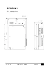
Страница 7: ...7 Version 1 0 1 DNP 211 User Manual 2022 06 01 2 Hardware 2 1 Dimensions...

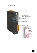
Страница 8: ...8 Version 1 0 1 DNP 211 User Manual 2022 06 01 2 2 Appearance...

Страница 9: ...illustration of these five LEDs LED Name LED Status Description PWR ON Power on OFF Power failure RUN Blink OS is running OFF OS stops running L1 Flash every second Firmware is running Other Firmware...

Страница 10: ...AN1 to an Ethernet hub switch and PC You can also link directly the DNP 211 to PC with an Ethernet cable After power is connected please wait 1 minute for DNP 211 start up procedure When the RUN indic...

Страница 11: ...01 3 3 2 DNP 211 Utility Introduction The DNP_211_Utility is as below DNP 211 Communication Configure Gateway Type Display gateway type of the DNP 211 Gateway IP Modbus TCP IP address of the DNP 211...

Страница 12: ...4 5 DNP3 Master ID Master ID cannot be the same as slave 0 65519 Modbus Slave ID Modbus ID of the DNP 211 Slave Amount Number of DNP3 slaves DNP3 Outstation Communication Configure Number tab Select...

Страница 13: ...ve map with Group_Variation Group_Variation Added I O type of the slave map with I O Type Start Index Added I O start address at the DNP3 slave Amount Amount of the I O item Output mode DO AO output m...

Страница 14: ...0 1 DNP 211 User Manual 2022 06 01 Upload Upload the GatewayConfig toml configuration file or d2m_xxxxxxxx tar gz firmware file to DNP 211 Note DNP 211 must be rebooted after upload configuration or f...

Страница 15: ...model DNP 211 3 4 2 DNP 211 Reader Introduction DNP 211 Reader is a simple test utility for DNP 211 module It can import the toml file produced by DNP 211 Utility and test the connection and I O func...

Страница 16: ...with DNP 211 module If successful DNP 211 Reader will show as below Disconnect Disconnect with PC and DNP 211 Status Connection status of all Outstations Modbus 30001 30032 0 The setting of the DNP 2...

Страница 17: ...three output forms DO bit DO full and AO output DO bit mode This mode can output several DO bits simply As above there are 7 DO points bit0 bit6 Fill the Start bit and Output Amount bits and input th...

Страница 18: ...terface only provides command options as for the detailed description and support of each function please refer to the instruction manual of the user s Outstation AO Output This mode can select AO cha...

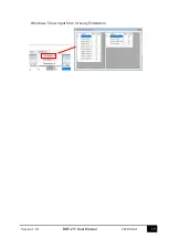
Страница 19: ...19 Version 1 0 1 DNP 211 User Manual 2022 06 01 Windows Show input form of every Outstation...

Страница 20: ...of Modbus and DNP3 as below Register field Modbus address 0xxxx DO 1xxxx DI 3xxxx AI 4xxxx AO Slave field DNP3 Outstation ID Group field I O type of the Outstation Variation field Variation of the I...

Страница 21: ...21 Version 1 0 1 DNP 211 User Manual 2022 06 01 Appendix B Mapping Rule...

Отзывы: