


10
Version 1.0.1
DNP-211 User Manual
2022/06/01
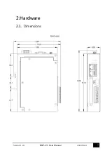
3.
Getting Started With DNP-211
3.1.
Preparations for Devices
In addition to the DNP-211, please prepare the following:
1.
Power Supply: +12 ~ +48 VDC
(Ex: DP-665)
2.
Ethernet Hub or Switch
(Ex: NS-205)
3.
PC/NB:
Can connect to the network and set the network
3.2.
Hardware Wiring
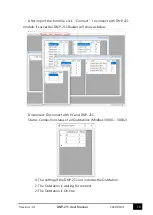
Connect the DNP-211 with the RJ-45 Ethernet port LAN1 to an Ethernet
hub/switch and PC. You can also link directly the DNP-211 to PC with an
Ethernet cable.
After power is connected, please
wait 1 minute
for DNP-211 start-up
procedure. When the
"RUN"
indicator starts
flashing
and
“PWR”
indicator is
constantly lit
, it represents the boot is complete. After the
module boots successfully, if the
"L1"
indicator flashes every second, it
means the firmware is running.
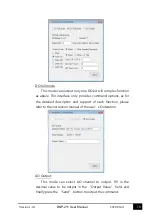
3.3.
DNP-211 Utility
3.3.1.
Download DNP-211 Utility
https://www.icpdas.com/en/download/show.php?num=8036&model=DNP-211
Download and install IEC850_211_S_Utility
Содержание DNP-211
Страница 1: ...User Manual Version 1 0 1 Jun 2022 DNP 211 DNP3 Master to Modbus TCP Server Gateway...
Страница 7: ...7 Version 1 0 1 DNP 211 User Manual 2022 06 01 2 Hardware 2 1 Dimensions...
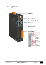
Страница 8: ...8 Version 1 0 1 DNP 211 User Manual 2022 06 01 2 2 Appearance...
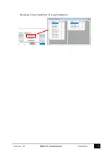
Страница 19: ...19 Version 1 0 1 DNP 211 User Manual 2022 06 01 Windows Show input form of every Outstation...
Страница 21: ...21 Version 1 0 1 DNP 211 User Manual 2022 06 01 Appendix B Mapping Rule...


