INSTRUCTION
Virtual Serial Port
Thank you for purchasing VE-PG3.
The Virtual Serial Port function of VE-PG3 allows you
to control a device with a serial communication interface,
through the
TCP/IP network.
READ ALL INSTRUCTIONS carefully and completely be-
fore using.
1. System requirements
(As of November 2012)
3. Adding the Virtual Serial Port
Operating System
• Microsoft
®
Windows
®
8
(32/64 bit)
• Microsoft
®
Windows
®
7
(32/64 bit: Service Pack1 or later)
• Microsoft
®
Windows Vista
®
(32/64 bit: Service Pack2 or later)
• Microsoft
®
Windows
®
XP
(32 bit: Service Pack3 or later 64 bit: Service Pack2 or later)
NOTE:
Microsoft
®
Windows
®
RT is not supported.
Because the system requirements may differ, depending on your PC environment, the operation is not guaranteed.
“Windows 7” is used for the descriptions in this instruction guide.
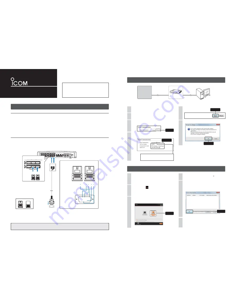
Connection
The Virtual Serial Port function of the VE-PG3 is designed to remotely control a device with a serial communication interface.
Connect the VE-PG3 and the serial device using the modifi ed RS-232C cable, as illustrated below.
• Verify that both the VE-PG3 and device are turned OFF when connecting or disconnecting the cable.
Example: Connecting an RS-232C cable with the 9-pin D-sub connector.
Insert the CD (UTILITY DISC) into a CD drive.
• You must log on as the administrator.
1
Double-click the
icon (APPLICATION FILE) con-
tained in the CD.
2
Click [Virtual Serial Port Manager] on the menu
screen.
3
If “User Account Control” appears, click [Yes] to continue.
4
5
When the installation is fi nished,
the COM port number
(Example: COM10) will appear in the above window.
• The COM port number may differ, depending on your PC
environment.
6
Click
T
o
the ser
ial comm
unication de
vice
LINE2
LINE1
PHONE
B C
B C
[EXT1] port (lower slot)
VE-PG3 (rear view)
VE-PG3 (rear view)
VE-PG3 (rear view)
B
C
Connectors
(Top side)
C1
WIRING
C2 C3 C4
B4
GND
TXD RXD RTS CTS
1 2 3 4
1 2 3 4
RS-232C
(9-pin D-sub connector)
t
q w e r
o
y u i
Top
Top
Top
Bottom
Bottom
Bottom
1 2 3 4
1 2 3 4
1 2 3 4
1 2 3 4
1 2 3 4
t
q w e r
o
y u i
t
q w e r
o
y u i
NOTE:
A data transmission delay may occur as the data routes through the network.
The error caused by the delay may be improved if the time out timer is set to a long value.
2. Preparation on the VE-PG3
• This is an example to connect the serial device to [EXT1] (lower slot) on the VE-PG3.
[EXT1]
[LAN]
VE-PG3
Serial
communication
device
LAN cable
(Purchase separately)
Connection cable
PC
(Example: 192.168.0.100)
192.168.0.1
(IP address on
the local area network)
Access the VE-PG3 setting screen.
• See the VE-PG3 instruction manual for details.
1
Click <Apply>.
4
Read the message, and then click <OK>.
5
Click the [Port Settings] menu, and then click
[EXT Output 1 (EXT1)].
2
Select “Enable.”
• The [Serial Communication] items will appear.
4
3
Click
• This is an example connecting the device
to [EXT1] (lower slot) on the VE-PG3.
• Use the spare connectors* which are
supplied with the VE-PG3.
*Manufacturer: DDK.
Name: 232D-04S1B-DA5-FA
When the Virtual Serial Port window appears, click
[Add].
• If a security warning dialog appears or the application asks
you to reboot the PC, follow the instructions.
(Up to 64 virtual serial ports can be added.)
Confi gure the [Serial Communication] items as shown
below.
(The screen may differ, depending on the setting.)
Select
Configure
The same TCP port number here must be set
as the Virtual Serial Port number.
(See the back side for details.)
Click
Click


