1-1-32 Kamiminami, Hirano-ku, Osaka 547-0003, Japan
A-7046-5EX © 2012 Icom Inc.
Icom, Icom Inc. and the Icom logo are registered trademarks of Icom Incorporated (Japan) in Japan, the United States, the
United Kingdom, Germany, France, Spain, Russia and/or other countries.
Adobe and Reader are registered trademarks of Adobe Systems Incorporated in the United States and/or other countries.
Microsoft, Windows and Windows Vista are registered trademarks of Microsoft
Corporation in the United States and/or other countries.
All other products or brands are registered trademarks or trademarks of their respective holders.
ALL RIGHTS RESERVED. This document contains material protected under International and Domestic Copyright Laws and
Treaties. Any unauthorized reprint or use of this material is prohibited. No part of this document may be reproduced or transmit-
ted in any form or by any means, electronic or mechanical, including photocopying, recording, or by any information storage and
retrieval system without express written permission from Icom Incorporated.
All stated specifi cations and design are subject to change without notice or obligation.
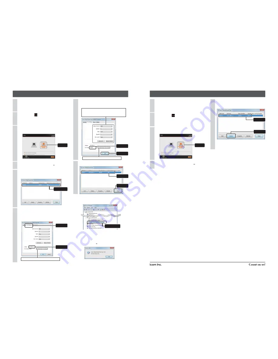
4. Configuring the Virtual Serial Port
If “User Account Control” appears, click [Yes] to continue.
4
If “User Account Control” appears, click [Yes] to con-
tinue.
4
When the Virtual Serial Port window appears, double-
click on the port to confi gure (Example: COM10).
5
The property window will appear.
Select the [Port Settings] tab in the property window,
and enter the VE-PG3's IP address (on the LAN)
(See the top side for details).
6
Enter the TCP port number (See the top side for de-
tails), and then click <OK>.
7
5. Deleting the Virtual Serial Port
When the Virtual Serial Port window appears, select
the port to delete (Example: COM10), and then click
[Delete].
5
Confi rm the port setting, and then click <Close>.
8
• To simultaneously delete multiple ports, select them while
holding down [Shift] or [Ctrl].
• If the application asks you to reboot the PC, follow the in-
structions.
Insert the CD (UTILITY DISC) into a CD drive.
• You must log on as the administrator.
1
Insert the CD (UTILITY DISC) into a CD drive.
• You must log on as the administrator.
1
Double-click the
icon (APPLICATION FILE) in the
window.
2
Double-click the
icon (APPLICATION FILE) con-
tained in the CD.
2
Click [Virtual Serial Port Manager] on the menu
screen.
3
Click [Virtual Serial Port Manager] on the menu
screen.
3
[For your information]
• You can open the property window in the Device Manager.
• [Address] on the [Port Settings] tab (In step 6) can also ac-
cept a domain name of up to 255 characters.
• Right-click on the title bar of the Virtual Serial Port window,
and then select [About(A)...] to open the [Version info] win-
dow, as shown below.
• “Virtual Serial Port Ver. 1.03.” is used for the descriptions in this
instruction guide.
Double-click
(This screen is an example.)
Double-click
q
Enter
w
Click
w
Enter
q
Select
Uncheck this item, or the data will not be encrypted.
Uncheck this item, or the data will not be encrypted.
Click
Click
If necessary, confi gure the serial port settings.
Modifying these settings affects only the Virtual Se-
rial Port function.
w
Click
q
Confirm
q
Select
w
Click


