background image

8

1

ATTACHMENT

8.   Connect the narrow flat cable to connector [J409], and 

then connect the wide flat cable to connector [J400].


D

Attaching the front panel (Continued)

9.   Put the shield cover and rubber cover back in the main 

unit.

10.  Put the main unit’s top cover back on.

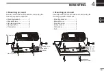
7.   Pass the flat cables through the opening in the main unit, and then attach the separation kit’s front panel to the main unit 

by pushing it in place.

[J409]

[J400]

Содержание RMK-5

Страница 1: ...INSTRUCTION MANUAL DUAL HEAD SEPARATION KIT RMK 7 SEPARATION KIT RMK 5...

Страница 2: ...re including but not limited to fires earthquakes storms floods lightning other natural disasters disturbances riots war or radioactive contamination The use of Icom products with any equipment that i...

Страница 3: ...ore attachment Exposing them to dust or water will result in serious damage to the transceiver and the separation kit BE SURE the transceiver power is OFF and the DC power cable is disconnected before...

Страница 4: ...nding screw 2 2 u Connector O ring 3 4 i Mounting bracket 1 2 o Bracket screw 2 4 0 Self tapping screw 4 8 1 Mounting screw 4 8 2 Spring washer 4 8 3 Flat washer 4 8 4 Nut 4 8 q w e r t y i o 0 u 1 2...

Страница 5: ...hone with the RMK 5 L Ask your dealers for details on the microphone Main unit Control head Front panel Rear panel NOTE You can only attach the HM 218 to the RMK 5 s front panel You cannot attach the...

Страница 6: ...OFF the transceiver and disconnect the DC power cable 2 Carefully pull out the side of the top cover in the direction of the arrow and then lift off the top cover Top cover Shield cover Be careful Do...

Страница 7: ...tach the control head from the main unit Attachment D D Opening the separation kit Front panel Rear panel NOTE The separation kit is supplied with the front panel and rear panel attached First you nee...

Страница 8: ...panel Separation cable Ground wire Control connector 4 Firmly slide the cable bracket in place to lock the cable inside the rear panel Cable bracket 5 Unfasten the grounding screw from screw hole 3 an...

Страница 9: ...l 2 Connect the flat cable on the transceiver s front panel and then connect the speaker cable you disconnected from the transceiver s main unit to J2 on the separation kit s rear panel 3 Firmly attac...

Страница 10: ...e pass that cable through the other cable hole Front panel Separation cable Ground wire Control connector 2 Firmly slide the cable bracket in place to lock the cable inside the front panel 3 Firmly fa...

Страница 11: ...5 Connect the narrow flat cable to connector J1 Recommendation for easy attachment Loosely bend the narrow flat cable LThe wide flat cable is originally bent Loosely Bend L If you are connecting anoth...

Страница 12: ...tor J400 D D Attaching the front panel Continued 9 Put the shield cover and rubber cover back in the main unit 10 Put the main unit s top cover back on 7 Pass the flat cables through the opening in th...

Страница 13: ...ese items Other Head is in use Except for the Power key VOL and Emer keys all keys are locked while one control head is being used and Other Head is in use is displayed as shown below The PTT button i...

Страница 14: ...D 1 HEAD 2 Select which control head or simply select both control heads to automatically start scanning after putting the microphone in the hanger on Hook L To use this function turn the Hook Scan fu...

Страница 15: ...to use when transmitting without pushing PTT such as when using the Auto TX function or PC commands HEAD 1 CONTROL HEAD 1 s microphone is used HEAD 2 CONTROL HEAD 2 s microphone is used D D Head SP o...

Страница 16: ...for command microphones 8 m 26 3 ft Some options may not be available in some countries Ask your dealer for details Specifications Audio output power 3 5 W with a 4 load at 5 distortion Operating tem...

Страница 17: ...racket screw 2 Self tapping screw 4 Spring washer 4 Flat washer 4 D D Mounting on a board Securely mount the control head on a board using the following supplied accessories Mounting bracket 1 Bracket...

Страница 18: ...MEMO...

Страница 19: ...MEMO 1 2 3 4 5 6 7 8 9 10 11 12 13 14 15 16...

Страница 20: ...1 1 32 Kamiminami Hirano ku Osaka 547 0003 Japan A7341D 1EX 1 Printed in Japan 2016 2017 Icom Inc...

Отзывы: