background image

i

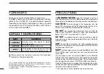
FOREWORD

Thank you for purchasing the RMK-4 

SEPARATION


KIT

.

The RMK-4 allows you to connect the additional CONTROL 
HEAD  to  the  IC-F9511HT  to  enable  dual-head  operation. 
Depending on the length of separation you need, use either 
the optional OPC-607, OPC-608, OPC-609 or OPC-726 

SEP

-

ARATION


CABLE

 with the RMK-4.

EXPLICIT DEFINITIONS

WORD

DEFINITION

R

WARNING

Personal  injury,  fire  hazard  or  electric 
shock may occur.

CAUTION

Equipment damage may occur.

NOTE

If disregarded, inconvenience only. No risk 
of personal injury, fire or electric shock.

Please refer to the instruction manual of the transceiver 
for details of the basic operation.

PRECAUTIONS

R

WARNING!  NEVER

  place  the  transceiver’s  main  unit 

(with the RMK-4) and CONTROL HEADs where normal operation of 
the vehicle may be hindered or where they could cause bodily injury.

CAUTION!

  To  avoid  damage  to  the  transceiver,  turn  the 

power OFF and disconnect the DC power cable from the trans-
ceiver’s main unit before disassemble the transceiver.

DO  NOT

  use  or  place  the  transceiver’s  main  unit  (with  the 

RMK-4)  and  CONTROL  HEADs  in  areas  with  temperatures 
below –30°C (–22°F) or above +60°C (+140°F).

DO  NOT

  use  chemical  agents  such  as  benzine  or  alcohol 

when cleaning, as they can damage the RMK-4 and CONTROL 
HEAD’s surfaces.

USE

 the specified microphone only. Other microphones have 

different pin assignments and may damage CONTROL HEAD or 
the transceiver’s main unit.

KEEP

 the transceiver’s main unit (with the RMK-4) and CON-

TROL  HEADs  away  from  heavy  rain,  and  never  immerse  them 
in the water.
The  transceiver’s  main  unit  (with  the  RMK-4)  and  CONTROL 
HEADs  meet  IP54  requirements  for  dust-protection  and  splash 
resistance when the optional microphone*, the front/rear plate(s) 
and the speaker jack cover of CONTROL HEAD are attached.
However, if these items are dropped, dust-protection and splash 
resistance cannot be guaranteed because of possible damage to 
the cases or the waterproof seals.
* The microphone is not dust-protection and splash resistant.

Icom, Icom Inc. and the Icom logo are registered trademarks of Icom Incor-
porated (Japan) in Japan, the United States, the United Kingdom, Germany, 
France, Spain, Russia and/or other countries.
All other products or brands are registered trademarks or trademarks of their 
respective holders.

Содержание RMK-4

Страница 1: ...INSTRUCTION MANUAL RMK 4 SEPARATION KIT...

Страница 2: ...unit with the RMK 4 and CONTROL HEADs in areas with temperatures below 30 C 22 F or above 60 C 140 F DO NOT use chemical agents such as benzine or alcohol when cleaning as they can damage the RMK 4 an...

Страница 3: ...lling the programmable function keys See at right for details The serial number seal is put here and labeled RMK 4 Function name stickers There are no labels on the programmable function keys since th...

Страница 4: ...F CONTENTS iii 1 CONNECTION 1 5 Removing the transceiver s main unit attachment 1 Connecting CONTROL HEAD and RMK 4 2 Attaching the RMK 4 4 Mounting 5 2 REMOTE BOX SET MODE 6 8 Set mode items 6 3 DUAL...

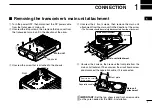
Страница 5: ...the arrow The flat cable should be carefully disconnected from the attachment Main unit attachment Main unit attachment Flat cable t Unscrew the 4 screws then remove the front plate from the main uni...

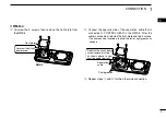
Страница 6: ...he circuit board screw w Connect the separation cable to CONTROL HEAD The cable can be inserted into either the left or right grooves as needed Separation cable Cable groove CONTROL HEAD Reinstall the...

Страница 7: ...ide of the separation cable that is connected to CONTROL HEAD to the RMK 4 After the cable is connected reinstall the front plate and the 4 screws The cable can be inserted into either the left or rig...

Страница 8: ...flat cable and the RMK 4 are connected attached correctly and not upside down w Replace the screw that was removed from the main unit in step e in p 1 to the chassis e Main unit RMK 4 RMK 4 w e Flat...

Страница 9: ...r securely with the 4 supplied screws to a solid surface Bracket screw D Overhead mounting Mount the controller securely with the 4 supplied screws to a solid surface which can support more than 2 kg...

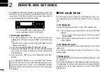
Страница 10: ...oth dual head and sin gle head operations are set in the USER SET MODE Please refer to the instruction manual of the transceiver for details Set mode items The following functions other than RX Speake...

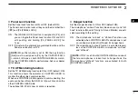
Страница 11: ...EAD to monitor the other side s communication When one CONTROL HEAD operator is communicating the audio can be heard from the SP 22 EXTERNAL SPEAKER on the other CONTROL HEAD side The optional SP 22 E...

Страница 12: ...adjustable by CONTROL HEADs D Intercom function Set the Intercom function to ON or OFF default ON The Intercom function allows CONTROL HEAD operators to communicate each other via their microphones Th...

Страница 13: ...al can be heard on the caller side s CONTROL HEAD external speaker and the main unit s external speaker When the message signal is received it is not displayed on the LCD of CONTROL HEADs during inter...

Страница 14: ...d the TX indicators lights red I N U S E NOTES Transmission can be performed on either CONTROL HEADs 1 or 2 at the same time The Power ON Password function will not work properly when attaching the RM...

Страница 15: ...y duty microphone HM 148T Self grounding heavy duty DTMF microphone SM 25 DESKTOP MICROPHONE SP 22 EXTERNAL SPEAKER Compact and easy to install Input impedance 4 Max input power 5 W The SP 22 is not r...

Страница 16: ...1 1 32 Kamiminami Hirano ku Osaka 547 0003 Japan A 6757H 1US q Printed in Japan 2009 Icom Inc...

Отзывы: