


9
3
DUAL-HEAD OPERATION
1
2
3
4
5
6
7
8
9
10
11
12
13
14
15
16
■
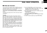
Intercom function
[P3] is used for the Intercom function ON/OFF switch when
the Intercom function is set to ON in the REMOTE BOX SET
MODE. (No other function can be assigned.)
The Intercom function allows the operators of CONTROL
HEAD 1 and 2 to communicate each other via their micro-
phones.
The optional microphone and the SP-22
EXTERNAL
SPEAKER
are required.
NOTE:
• Transmitting is impossible during intercom operation.
• During intercom operation, when [PTT] is pushed and
held on the caller’s side, any received radio signal is
muted on the listener side’s CONTROL HEAD external
speaker. However, the received radio signal can be heard
on the caller side’s CONTROL HEAD external speaker
and the main unit’s external speaker.
• When the message signal is received, it is not displayed
on the LCD of CONTROL HEADs during intercom opera-
tion. After exiting the intercom mode, it will be displayed
on the LCD.
• During intercom operation, CONTROL HEADs 1 and 2
return to the normal operation mode, if no [PTT] opera-
tion is performed for 30 sec.
q
Push [P3 (INTERCOM)] to enter the intercom mode.
• The other CONTROL HEAD is also set to the Intercom mode
automatically even if this function is set to OFF.
• “INTERCOM” appears on both CONTROL HEADs.
w
Push and hold [PTT] and speak at a normal voice level
into the microphone.
• “IN USE” blinks on the listener side.
• To adjust the audio output level, rotate [VOL].
e
After releasing [PTT] you can hear the response through
the speaker.
r
To return to normal operation, push [P3 (INTERCOM)].


