•
•
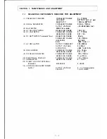
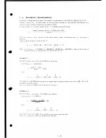
2. Se the channel select switch at a programmed channel.
•
I
n he recei
e
mode,
adjust
L211
for the
programmed receiving frequency minus 10.695MHz.
•
In he ransmit
mode,
adjust
L 212 for the programmed transmitting frequency.
•
S
e
he channel
at a duplex
channel,
and adjust
L213
for the desired transmitting frequency.
•
en chec again,
because
these
adjustments interact.
3. Con irma ion
Chee eac frequency:
JI
requencies
should
be within
±500Hz.
7
·
5
·
2
TRA NSMISSI ON
3
.
Po· e
dj s
ent
2.
3 .
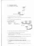
Connec
ion
o
measuring
instruments and setting of the knobs.
nect
T o 50 ohm power meter.
•
C
o
ec
2
ol
meter
and
variable voltage power supply to the set.
CAUTIO
:
Applying over 10.SV can damage the P.A. transistor.
•
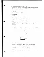
Se
e
channel
select switch
at a programmed channel.
hrough
L222
and
C285, C286,
C290
and C291 for maximum power output while
s
i
g
P
T s
i
ch.
rren
drain
exceeds
800mA, adjust C291 to set the current at 800mA, and repeat
res.
output, less than 800mA current drain.
\o aonor ali
in
operation
should
be found if the supply voltage is varied from 5.5V to 1 0 .SV.
stment
Power
Supply
(5�11V)
RF
wattmeter
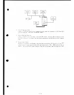
e measuring instrument and the settings of the controls.
T Connector to a deviation meter with a directional coupler or attenuator.
e
e e
ilter
shall
be
a High Pass Filter 50Hz, L.P.F.
2 0KHz.
De-emphasis OFF.
a,nel
s
e
l
ec
t
switch
at a
programmed channel.
•
Co
F
oscillator, with AF millivoltmeter in parallel, to the mic input.
1KH z 120mV R MS. During transmit, adjust R171 on the main unit for
7-7
Содержание IC-H12
Страница 1: ...VHF RADIOTELEPHONE 12 channels l C H 2 MAINTENANCE MANUAL...
Страница 50: ...PLL UNIT IL w c 8 2 0 0...


