•
•
7-5
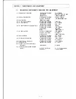
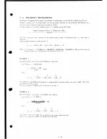
BAS IC ALIGNMENT PROCEDURE
7. 5
-
1
P. L. L. CI R CU I T
A.
Loe Adjus ment
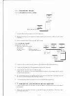
1. Connect the measuring instrument and set the control knobs as follows"
•
C
onnec
t an oscilloscope (l OMHz band width) to R21 7.
2
.
•
C
onn
e
c
t
oltmeter between R205 and ground.
•
S
e
he
channel
select
switch at a programmed channel (center frequency of the operating
ency range is recommended).
Power
Supply
(8.4V)
Oscillo scope
RF
Watt meter
R 21 7
PLL
R205
Frequency
Counter
Multimeter
e
circ
i
is operating
normally,
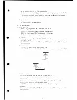
adjust
coil
L203.
The
P. L.
L. wi II lock.
e
coil
o
L203, and the voltage of
R 205 varies between 0
�
5V, and P. L. L. should lock.
or 2V after lock .
L216 for maximum
voltage (P- P value) on the oscilloscope and then
ss
on
L215
to
max imum.
Set the channel select
switch
at a high edge fre·
e,
a
d repeat
adjustment
of L215,
L 216
several times. After that, confirm the
.
o
age
of
205
(both
transmission
and receiving) 2V ±0. 3V at
center
frequency and
�e
.
o
age
o
R 21 7
(bo
transmission
and receiving) is over 2Vp-p (over operating range
o
'
e
P
.
.
L . on't
lock,
check these
voltages:
R+5V, T +5V, 5V constant, and the
of IC203.
eoue c Adjustment
e measuring instruments and the setting of knobs.
•
.'.
e adjus
g t e receiving
frequency,
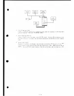
connect the frequency counter to R 25 7 through a
er
po
adjustment,
loosely
couple the
set to a frequency counter with ca-
o"
ore
an
170MHz (with
dummy
load
connected), so that the transmitting fre-
ca
ob ained.
0
R257
(P LLI
7- 6
Dummy
Load
Frequency
Counter
(TX)
(RX)
Содержание IC-H12
Страница 1: ...VHF RADIOTELEPHONE 12 channels l C H 2 MAINTENANCE MANUAL...
Страница 50: ...PLL UNIT IL w c 8 2 0 0...


