


(Replacement page)
Jun. 2012
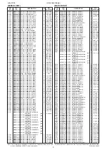
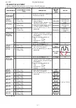
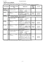
• TRANSMIT ADJUSTMENT
1) Select an adjustment item using cursor or [
↑
] / [
↓
] keys of the PC’s keyboard.
2) Set or modify the adjustment value as specifi ed using [
←
] / [
→
] keys of the PC’s keyboard, then push the [ENTER] key.
ADJUSTMENT
ADJUSTMENT CONDI-
TION
OPERATION
ADJUST-
MENT
ITEM
VALUE
TX
Output Power
-Preparation-
1
–
• Connect an RF power meter to the
TX antenna connector.
–
–
-Adjust-
(Hi Power)
2 • CH. : 1-6
• Transmitting
1) While transmitting, set the power
supply voltage as;
[EUR-01], [DPM-01], [DPM-02] : 13.2 V
Other than above versions : 13.6 V
2) Adjust the TX output power using [
←
]
/ [
→
] keys of the PC’s keyboard.
3) Push the [ENTER] key to store the
adjust value.
[Power(Hi)]
50 W [50 W ver.]
25 W [25 W ver.]
5.0 W*
(L2 Power)
3 • CH. : 1-7
• Transmitting
[Power(L2)]
25 W [50 W ver.]
10 W [25 W ver.]
5.0 W*
(L1 Power)
4 • CH. : 1-8
• Transmitting
[Power(L1)]
5 W [50 W ver.]
2.5 W [25 W ver.]
5.0 W*
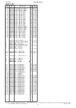
MODULATION
BALANCE
-Preparation-
1
–
1) Connect a modulation analyzer to
the TX antenna connector through
an attenuator.
2) Set the modulation analyzer as;
HPF
:
OFF
LPF
: 20 kHz
De-emphasis
:
OFF
Detector
:
(P-P)/2
–
–
2
–
• Set the item
[TX Mode]
to "2."
[TX Mode]
"2"
-Adjust-
(VCO 1)
3 • CH. : 1-9
• Transmitting
1) Adjust the wave form using [
←
] / [
→
]
keys of the PC’s keyboard.
2) Push the [ENTER] key to store the
adjust value.
[BAL]
(VCO 2)
4 • CH. : 1-10
• Transmitting
[BAL Offset
(High]
DIGITAL
DEVIATION
-Preparation-
1
–
• Set the item
[TX Mode]
to "16."
[TX Mode]
"16"
2
–
1) Connect a modulation analyzer to
the TX antenna connector through
an attenuator.
2) Set the modulation analyzer as;
HPF
:
OFF
LPF
: 20 kHz
De-emphasis
:
OFF
Detector
:
(P-P)/2
–
–
-Adjust-
(Band 1)
3 • CH. : 1-11
• Transmitting
1) Adjust the deviation using [
←
] / [
→
]
keys of the PC’s keyboard.
2) Push the [ENTER] key to store the
adjust value.
[MOD
(Digital)]
±1.35 to ±1.39 kHz
(Band 2)
4 • CH. : 1-12
• Transmitting
[MOD Slant
Band 0]
(Band 3)
5 • CH. : 1-13
• Transmitting
[MOD Slant
Band 1]
(Band 4)
6 • CH. : 1-14
• Transmitting
[MOD Slant
Band 2]
(Band 5)
7 • CH. : 1-15
• Transmitting
[MOD Offset
(High)]
(Band 6)
8 • CH. : 1-16
• Transmitting
[MOD Slant
Band 3]
(Band 7)
9 • CH. : 1-17
• Transmitting
[MOD Slant
Band 4]
(Band 8)
10 • CH. : 1-18
• Transmitting
[MOD Slant
Band 5]
*; For IC-FR5100H.
6 - 7
No over or under shoot.
As flat as possible.
Содержание iC-FR5000
Страница 62: ...SERVICE MANUAL ADDENDUM CONTENTS PARTS LIST 1 BOARD LAYOUTS 9 VOLTAGE DIAGRAM 11 Mar 2011...
Страница 106: ...SERVICE MANUAL ADDENDUM CONTENTS REPLACEMENT PAGES 6 4 6 5 PARTS LIST 1 VOLTAGE DIAGRAM 10 Jun 2009...
Страница 122: ...SERVICE MANUAL ADDENDUM CONTENTS REPLACEMENT PAGES 6 8 and 6 9 PARTS LIST 1 VOLTAGE DIAGRAM 9 Aug 2008...
Страница 138: ...S 14425XZ C1 Jun 2008 VHF FM REPEATER...
Страница 144: ...2 2 FRONT UNIT FRONT CPU IC503 CLOCK OSC X501 LCD DRIVER IC500 ANALOG SW IC506 AF POWER AMP IC509 SPEAKER SW Q508...
Страница 181: ...1 1 32 Kamiminami Hirano ku Osaka 547 0003 Japan S 14425XZ C1 2008 Icom Inc...


