


3 - 2
MAIN
MAIN
J9
J9
J9
J4
J4
Unscrew
ANT case
Unsolder
ANT case
Flat cable
Disconnect
Disconnect
Black
Black
Black
Black
Red
Red
Red
Red
W4
W4
Unsolder 2 points
Unsolder 4 points
Unscrew
Clip
15 screws
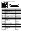
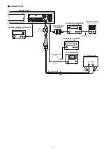
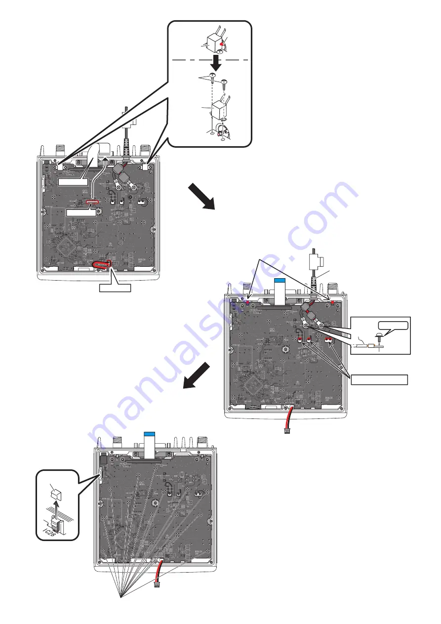
w
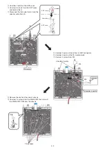
Unsolder 2 points at the ANT cases.
e
Unscrew 4 screws from the ANT cases,
and remove them.
r
Disconnect the flat cabe from J4 and the
speaker cable from J9.
t
Unsolder 2 points at the bottom of ANT connectors.
y
Unsolder 4 points at the PA module leads.
u
Unscrew 2 screws from W4.
i
Remove the clip from the side of chassis.
o
Unscrew 15 screws from the MAIN UNIT, then take off
the MAIN UNIT PCB from the chassis.
Содержание iC-FR5000
Страница 62: ...SERVICE MANUAL ADDENDUM CONTENTS PARTS LIST 1 BOARD LAYOUTS 9 VOLTAGE DIAGRAM 11 Mar 2011...
Страница 106: ...SERVICE MANUAL ADDENDUM CONTENTS REPLACEMENT PAGES 6 4 6 5 PARTS LIST 1 VOLTAGE DIAGRAM 10 Jun 2009...
Страница 122: ...SERVICE MANUAL ADDENDUM CONTENTS REPLACEMENT PAGES 6 8 and 6 9 PARTS LIST 1 VOLTAGE DIAGRAM 9 Aug 2008...
Страница 138: ...S 14425XZ C1 Jun 2008 VHF FM REPEATER...
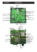
Страница 144: ...2 2 FRONT UNIT FRONT CPU IC503 CLOCK OSC X501 LCD DRIVER IC500 ANALOG SW IC506 AF POWER AMP IC509 SPEAKER SW Q508...
Страница 181: ...1 1 32 Kamiminami Hirano ku Osaka 547 0003 Japan S 14425XZ C1 2008 Icom Inc...


