


3 - 1
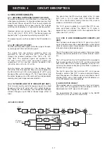
SECTION 3
DISASSEMBLY INSTRUCTION
E
E
LO
G
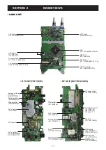
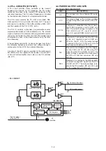
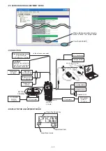
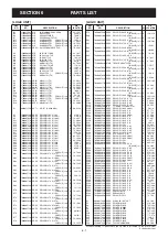
IC/RF unit
Front panel
A
D
B
F
J4
J4
C
J
I
J
LO
G
IC unit
RF unit
J
H
G
RF unit
L
M
L
K
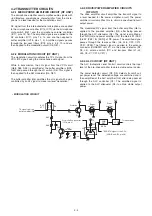
Be careful not to break and lost the sealing washer.
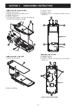
• REMOVING THE CHASSIS PANEL
1
Remove the Jack cap
A
.
2
Remove [VOL] knob
B
and [DIAL] knob
C
.
3
Unscrew the ANT nut
D
.
4
Unscrew 3 screws
E
.
5
Disconnect the connector
F
from J4 and remove the
LOGIC/RF unit from the Front panel.
• REMOVING THE LOGIC UNIT
1
Remove the main seal
G
.
• REMOVING THE RF UNIT
1
Unsolder 2 points
K
.
2
Unscrew 6 screws
L
.
3
Unscrew 2 screws
M
and remove the RF unit from the
chassis unit.
2
Unsolder 1 point
H
.
3
Unscrew 2 nuts
I
.
4
Unscrew 3 screws
J
and remove the LOGIC unit from
the RF unit.
Continue to right above.


