

4 - 4
4-2 TRANSMITTER CIRCUITS
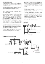
4-2-1 MICROPHONE AMPLIFIER CIRCUIT (RF UNIT)
The microphone amplifier circuit amplifies audio signals with
+6 dB/octave pre-emphasis characteristics from the micro-
phone to a level needed for the modulation circuit.
AF signal from the internal/external microphone are applied
to the microphone amplifier (IC15, IC19) via the microphone
mute switch (Q51) and the microphone volume controller
(IC17; pins 15, 16). The amplified signals are applied to the
AF controller (IC17, pins 13, 14, and are then applied to
buffer amplifier (IC18, pins 1, 2). Amplified signals passes
through the low-pass filters (IC18, pins 4, 5, 8, 10) and are
then applied to the modulation circuit (D5, D51).
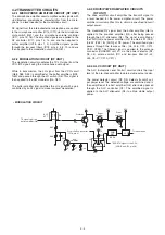
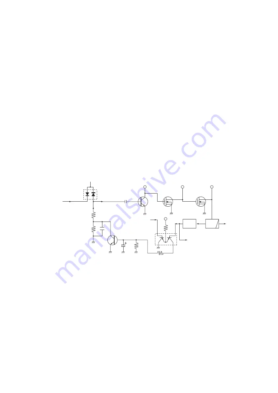
4-2-2 MODULATION CIRCUIT (RF UNIT)
The modulation circuit modulates the TX LO signal from the
VCO (RF signal) using the microphone audio signal.
While in transmission, the LO signal from the VCO circuit
(Q58, D38, D48) is amplified at the buffer amplifiers (Q28,
Q60) and passed through the LO switch (D6). This signal is
then applied to the AM modulator (D5, D51).
The buffer amplifier (Q6) amplifies the LO signal with a gain
controlled by an AF signal to make low level modulation.
TX signal from the
buffer amplifier (Q6)
ALC
ATT
D4
R25
R26
C38
Q5
C37
R24
R23
C38
From the D/A converter
(IC16, pin 4)
ALC
amplifier
Pre-drive
Q4
Q3
Q2
T5
T5
Q1
R11
VCC
VCC
amplifier
Driver
amplifier
Power
PWR
DET
LPF
To the antenna
D2, D3
"RFDETV" signal to the CPU
(LOGIC unit; IC1, pin 30)
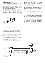
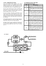
4-2-3 DRIVE/POWER AMPLIFIER CIRCUITS
(RF UNIT)
The drive amplifier circuit amplifies the transmit signal to
a level needed for the power amplifier circuit. The power
amplifier circuit amplifies this to obtain a specified transmit
output power.
The modulated RF signal from the buffer amplifier (Q6) is
applied to the pre-drive amplifier (Q4) after being passed
through the ALC attenuator (D4). The signal is amplified at
the YGR (Q3) and power amplifier (Q2) to obtain 5 W (PEP)
(3.6 W (PEP) for [EUR]) of RF power. The amplified signal
passes through the low-pass filter (L6, L46, C22, C212,
C297, C299). The filtered signal is applied to the antenna
connector (CHASSIS unit; J1) via the power detector (D2,
D3, L5), antenna switch (D1) and low-pass filter (L1–L3,
L45, C3–C7, C210, C211).
4-2-4 ALC CIRCUIT (RF UNIT)
The ALC (Automatic Level Control) circuit controls the input
level of the pre-drive amplifier to obtain stable output power.
The power detector circuit (D2, D3) detects transmit out-
put power level. The detected voltage are combined and is
then amplified at the ALC amplifier (Q5) after being passed
through the ALC controller (Q1). The amplified signal is
applied to the ALC attenuator (D4) to obtain stable output
power.
• MODULATION CIRCUIT


