1-1-32 Kamiminami, Hirano-ku, Osaka 547-0003, Japan
Apr. 2021
A7022D-3EX-4
Printed in Japan
© 2012–2021 Icom Inc.
¤6
DSC Settings
D
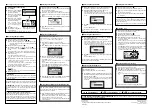
Automatic Acknowledgement
q
Enter either “INDIVIDUAL ACK,” “POSITION ACK” or “TEST
ACK” in the DSC Settings menu.
w
Rotate Dial to select “Auto TX” or “Manual TX,” then push
[ENT].
• Push [BACK] to cancel and return to the DSC Settings menu.
e
Push [EXIT] to return to the normal operating mode.
D
Channel Auto Switch function
(For only USA version.)
q
Enter “CH AUTO SWITCH” in the DSC Settings menu.
w
Rotate Dial to set the Channel Auto Switch function to “Auto
(No Delay),” “10 Second Delay” or “OFF,” then push [ENT].
• Push [BACK] to cancel and return to the DSC Settings menu.
e
Push [EXIT] to return to the normal operating mode.
D
Channel 16 Switch function
q
Enter “CH 16 SWITCH” in the DSC Settings menu.
w
Rotate Dial to set the Channel 16 Switch function to “Auto
(No Delay),” “10 Second Delay” or “OFF,” then push [ENT].
• Push [BACK] to cancel and return to the DSC Settings menu.
e
Push [EXIT] to return to the normal operating mode.
D
DSC Data Output
q
Enter “DSC DATA OUTPUT” in the DSC Settings menu.
e
Rotate Dial to set the DSC Data Output function to “All Sta-
tion,” “List Station” or “OFF,” then push [ENT].
• Push [BACK] to cancel and return to the DSC Settings menu.
e
Push [EXIT] to return to the normal operating mode.
D
Alarm
q
Enter “ALARM” in the DSC Settings menu.
w
Rotate Dial to select the status, then push [ENT].
• Push [BACK] to cancel and return to the DSC Settings menu.
• “ Safety,” “Routine,” “Warning,” “Self-Terminate” and “Discrete”
are selectable. (default: ON )
e
Rotate Dial to set the Alarm setting to “ON” or “OFF.”
r
Push [EXIT] to return to the normal operating mode.
D
Channel 70 Squelch level
q
Enter “CH 70 SQL LEVEL” in the DSC Settings menu.
w
Rotate Dial to adjust the squelch level until the noise just
disappears, then push [ENT].
• Push [BACK] to cancel and return to the DSC Settings menu.
e
Push [EXIT] to return to the normal operating mode.
D
DSC Loop Test
q
Enter “DSC LOOP TEST” in the DSC Settings menu.
w
Push [ENT] to start the DSC loop test.
• Push [BACK] to cancel and return to the DSC Settings menu.
• When the transmit DSC and receive DSC signals are matched,
“OK” appears.
e
Push [EXIT] to return to the normal operating mode.
If “NG” appears in step
w
, either or both TX and RX DSC
circuits has a problem. In that case, you will have to send
the transceiver to your nearest dealer for repair.
¤7
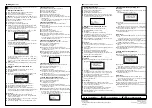
Intercom operation
This function is not available with the IC-M400BB.
q
Push [INCM] to enter the Intercom mode.
w
Hold down [INCM CALL] to sound the intercom beeps.
• The transceiver and the command microphone sound beeps
while holding down [INCM CALL].
• “CALL” appears.
e
After releasing [INCM CALL], hold down [PTT] and speak
into the microphone at a normal voice level.
• “TALK” appears on the caller’s display, or “LSTN” appears on
the listener’s display.
• To adjust the HM-195’s intercom volume level, rotate [VOL/
SQL](Dial) on the HM-195.
r
After releasing [PTT] you can hear the response through
the speaker.
t
To return to the normal operating mode, push [EXIT].
¤8
RX Speaker function
q
Push [RX
] to enter the RX Speaker mode.
• The RX Speaker volume level adjustment screen is displayed.
w
Rotate Dial or push [
Y
]/[
Z
]/[
Ω
]/[
≈
] to adjust the RX Speak-
er volume level, and then push [ENT].
• “RX
” appears.
e
To return to normal operating mode, push [RX
].
• “RX
” disappears.
¤9
PA (Public Address) function
q
Push [PA] to enter the Public Address mode.
w
Hold down [PTT] and speak at a normal voice level.
• While holding down [PTT], the screen below is displayed.
• To adjust the PA volume level, rotate Dial.
e
Push [EXIT] to return to normal operating screen.
‹0
Horn function
q
Push [HORN] to enter the Horn mode.
w
Hold down [HORN] to sound a horn.
• While holding down [HORN], the horn sounds, and the screen
below is displayed.
• To adjust the horn volume level, rotate Dial.
e
Push [EXIT] to return to the normal operating screen.
‹1
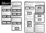
Menu screen operation
The Menu screen is used to change the transceiver’s functions
and the microphone’s own functions, send DSC calls or show
the entered MMSI and ATIS*
1
codes and GPS information*
2
.
*
1
Appears only when the transceiver is the Dutch or German ver-
sion.
*
2
Appears only when a GPS receiver compatible with NMEA0183
ver. 2.0 or 3.01 is connected to the transceiver.
These instructions are for only the microphone’s own func-
tions. Refer to the transceiver’s manual for the settings of
the other functions. (Some functions cannot be selected
from the HM-195.)
D
Entering the Menu screen and operation
q
Push [MENU].
w
Rotate Dial or push [
∫
]/[
√
] to select the root item, and then
push [ENT].
e
Rotate Dial or push [
∫
]/[
√
] to select the item, and then push
[ENT].
r
Rotate Dial or push [
∫
]/[
√
] to select the option, and then
push [ENT] to set it.
t
Push [EXIT] to exit the Menu screen.
• Push [CLEAR] or [BACK] to return to the previous screen.
•
Backlight
The function display and keys of the HM-195 can be backlit for
better visibility under low light conditions.
The backlight can be set to 7 levels and OFF.
(Default: 7)
•
Display contrast
The contrast of the HM-195’s function display can be adjusted
in 8 steps.
Level 1 is the lowest contrast, and level 8 is the highest con-
trast.
(Default: 5)
•
Key Beep
You can turn OFF beep tones for silent operation, or you can
turn ON the tones to have confirmation beeps sound when a
key is pushed.
(Default: ON)
•
COMMANDMIC Speaker
The HM-195’s external speaker can be used instead of the in-
ternal speaker.
(Default: Internal Speaker)
Regardless of this setting, the transceiver’s microphone
speaker is ON.
On the caller’s display
On the listener’s display
+
See “Instructions
q
”
(
z
to
⁄5
)
or “Instructions
w
”
(
⁄6
to
¤2
)
for other functions.
■
TIP
If the transceiver supports, you can use the AIS functions and
the Highway function with the HM-195. Push
to display
the Plotter screen or the Highway screen on the command mi-
crophone screen.
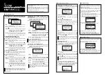
D
Plotter screen
3
5
4
2
1
q
TARGET BOX
2
YOUR VESSEL ICON
The vessel icon automatically points in the direction your
vessel is heading, in 45 degree steps.
When your vessel moves less than 2 knots per hour speed,
is displayed.
3
TARGET ICONS
AIS target: Vessel
AIS target: Vessel (Friend)
AIS target: AIS-SART, AIS-MOB, and EPIRB-AIS
* AIS target: Search and Rescue (SAR) aircraft
AIS target: Aids to Navigation (AtoN)
AIS target: Aids to Navigation (AtoN) virtual
* AIS target: Base station
* Waypoint: During navigation.
* MOB
* Blinks when the AIS target is closer than your CPA and
TCPA settings (Danger target).
4
DISPLAY RANGE
5
DISPLAY FILTER INDICATOR
Displayed when the type of targets on the Plotter screen is
filtered.
D
Highway screen
1
1
2
3
4
1
XTE LIMIT LINE
2
YOUR VESSEL ICON
When your vessel moves less than 2 knots per hour speed,
is displayed.
3
RANGE
Displays the range (RNG) from your vessel to the target.
4
XTE
Displays the Cross Track Error.


