Chapter 2 Installations
CI7BM User’s Manual
15
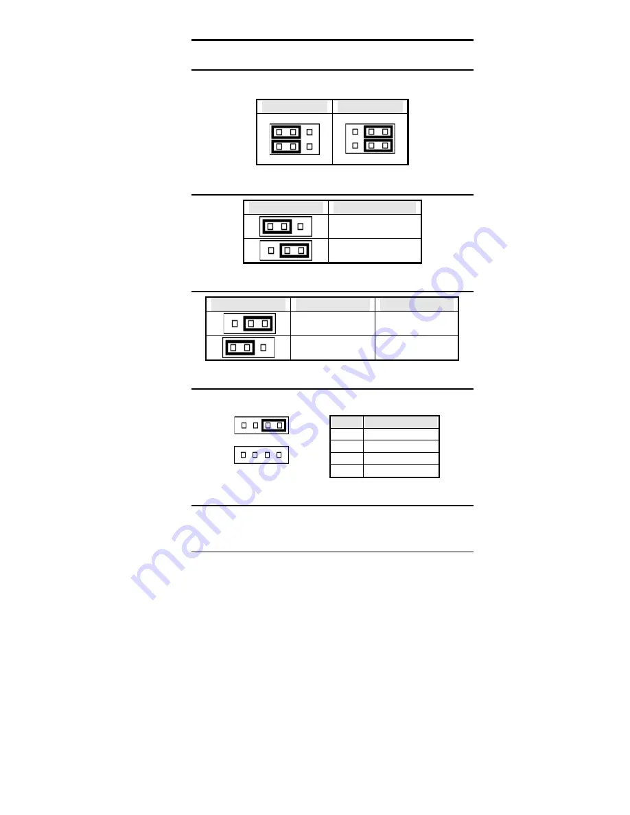
JP1: LCD Power Setting
The CI7BM XGA interface supports 5V and 3.3V LCD displays. Use
JP1 to change between 5V (
default
) and 3.3V panel video signal level.
3.3V Setting
5V Setting
2 4 6
1 3 5
2 4 6
1 3 5
JP4: DiskOnChip BIOS Expansion Address Select
JP4
Address
1
3
D0000-D7FFF
1
3
D8000-DFFFF (default)
JP5: Clear CMOS Content
JP5
Setting
Function
1
3
Pin 2-3
Short/Closed
Clear CMOS Content
1
3
Pin 1-2
Short/Closed
Normal Operation
JP7: External Battery Connector
JP7connects to an external battery to maintain the information stored in
the CMOS RAM in case the built-in battery malfunctions.
Pin #
Signal Name
1
Vcc
2
N.C.
3 Battery
GND
4 Ground
1
4
Internal Battery (default)
1
4
External Battery
JP8: On Board VGA Enable/Disable
The on board VGA jumper, by default, is set to
VGA Enable
(pin 1-2
short). To disable the VGA, short pin 2-3.
Содержание CI7BM
Страница 11: ...Chapter 1 Introduction CI7BM User s Manual 7 Board Dimensions ...
Страница 17: ...Chapter 2 Installations CI7BM User s Manual 13 Jumper Locations on the CI7BM ...
Страница 22: ...Chapter 2 Installations 18 CI7BM User s Manual Connector Locations on the CI7BM ...
Страница 41: ...Chapter 2 Installations CI7BM User s Manual 37 This page was intentionally left blank ...
Страница 67: ...Chapter 3 BIOS Configuration CI7BM User s Manual 63 This page was intentionally left blank ...
Страница 83: ...Chapter 7 LAN Driver Installation Guide CI7BM User s Manual 79 This page was intentionally left blank ...
Страница 87: ...Chapter8 System Monitor Utility CI7BM User s Manual 83 2 Power displays the current voltage status ...
Страница 88: ...Chapter 8 System Monitor Utility 84 CI7BM User s Manual 3 Memory displays the current memory usage status ...
Страница 99: ...Chapter 9 LANDesk Client Manager CI7BM User s Manual 95 This page was intentionally left blank ...
Страница 111: ...Appendix CI7BM User s Manual 107 Appendix A I O Port Address Map B Interrupt Request Lines IRQ ...


