background image

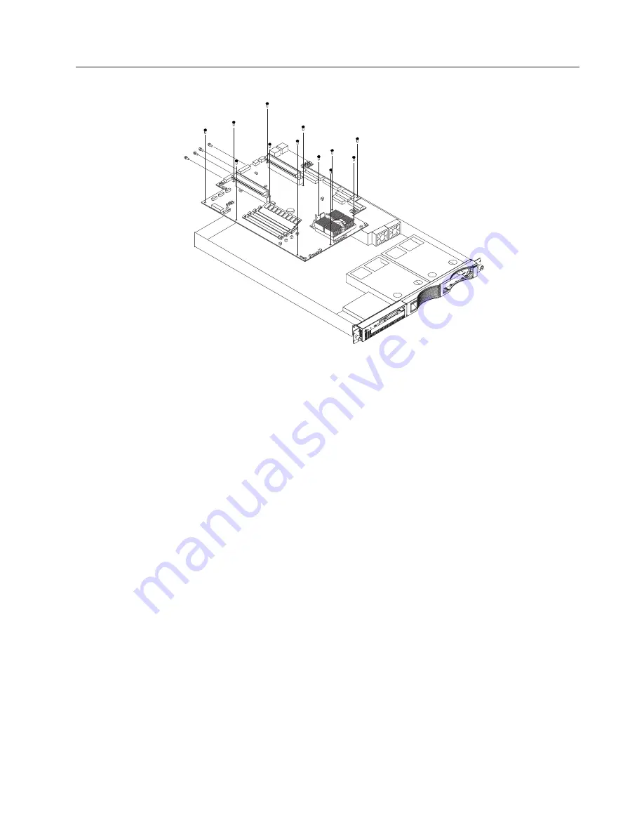
System board

To remove the system board:

Note:

Read“Safety information” on page 75 and “Before you begin” on page 36.

1.

Power off the server.

2.

Remove the cover. See “Removing the cover” on page 38.

3.

Disconnect all cables from the system board.

4.

Remove the adapter retaining latch (see “Removing a microprocessor” on
page 49).

5.

Remove the microprocessors. See “Removing a microprocessor” on page 49.

6.

Remove the memory modules. See “Installing DIMMs” on page 45.

7.

Remove screws from the system board.

8.

Remove the four screws from the rear of the server.

9.

Pull up on the system board to remove from the chassis.

Chapter 5. Installing Options

39

Содержание xSeries 300

Страница 1: ...Hardware Maintenance Manual xSeries 300 ...

Страница 2: ......

Страница 3: ...Hardware Maintenance Manual xSeries 300 ...

Страница 4: ...hical errors Changes are periodically made to the information herein these changes will be incorporated in new editions of the publication IBM may make improvements and or changes in the product s and or the program s described in this publication at any time This publication was developed for products and services offered in the United States of America IBM may not offer the products services or ...

Страница 5: ...ned servicers who are familiar with IBM PC Server products Important safety information Be sure to read all caution and danger statements in this book before performing any of the instructions Leia todas as instruções de cuidado e perigo antes de executar qualquer operação Prenez connaissance de toutes les consignes de type Attention et Danger avant de procéder aux opérations décrites par les inst...

Страница 6: ...evar a cabo cualquier operación Online Support Use the World Wide Web WWW to download Diagnostic BIOS Flash and Device Driver files File download address is http www us pc ibm com files html IBM Online Addresses The HMM manuals online address is http www us pc ibm com cdt hmm html The IBM PC Company Support Page is http www us pc ibm com support index html The IBM PC Company Home Page is http www ...

Страница 7: ...Utility program 30 Starting the Configuration Setup Utility program 30 Using the SCSISelect utility program some models 30 Starting the SCSISelect utility program 30 Using the PXE boot agent utility program 31 Starting the PXE boot agent utility program 31 Using the ServerGuide CDs 32 ServerGuide startup problems 33 Chapter 5 Installing Options 35 Major components of the xSeries 300 server 36 Befo...

Страница 8: ... General safety 75 Electrical safety 76 Safety inspection guide 77 Handling electrostatic discharge sensitive devices 78 Grounding requirements 79 Safety notices multi lingual translations 79 Send us your comments 108 Problem determination tips 109 Notices 109 Trademarks 110 vi Hardware Maintenance Manual xSeries 300 ...

Страница 9: ...stems sharing the same external storage device s Prior to running diagnostics verify that the failing system is not part of a shared DASD cluster A system might be part of a cluster if v The customer identifies the system as part of a cluster v One or more external storage units are attached to the system and at least one of the attached storage units is additionally attached to another system or ...

Страница 10: ...2 Hardware Maintenance Manual xSeries 300 ...

Страница 11: ...e data storage The xSeries 300 server comes with a three year limited warranty and IBM Server Start Up Support If you have access to the World Wide Web you can obtain up to date information about your xSeries 300 model and other IBM server products at the following World Wide Web addresses http www ibm com eserver xseries http www ibm com 1 Racks are marked in vertical increments of 1 75 inches ea...

Страница 12: ...Ethernet controllers on the system board with Alert on LAN 2 support v Serial port v Two USB ports v Keyboard port v Mouse port v Dual channel bus mastering IDE controller Hard disk controller v All models Dual channel bus mastering IDE controller v Some models SCSI adapter Adaptec Ultra160 is installed in one of the expansion slots Acoustical noise emissions v Sound power idling 6 6 bel maximum v...

Страница 13: ...re information v Integrated network environment support Your server comes with two Intel Ethernet controllers on the system board These Ethernet controllers have an interface for connecting to 10 Mbps or 100 Mbps networks The server automatically selects between 10BASE T and 100BASE TX environments The controller provides full duplex FDX capability which enables simultaneous transmission and recep...

Страница 14: ...rogram load IPL power supply Automatic error retry or recovery Automatic server restart Automatic restart after power failure Built in menu driven configuration programs Built in menu driven setup programs Failover Ethernet support Menu driven diagnostic programs on CD ROM Microsoft Windows NT failover support Monitoring support for temperature voltage and fan speed Server management Wake on LAN c...

Страница 15: ...your server and it blinks when the server is in standby mode Reset button Press this button to reset the server and run the power on self test POST You might need to use a pen or the end of a straightened paper clip to press the button System error light This amber LED lights when a system error occurs Diskette drive activity light When this LED is on it indicates that the diskette drive is in use...

Страница 16: ...on light This green LED lights and stays on when you turn on your server and will blink when the server is in standby mode This light duplicates the power on light on the front of the server Video port The signal cable for a monitor connects to the video port Serial port Signal cables for modems or other serial devices connect to the serial port USB 2 This is an automatically configured port that ...

Страница 17: ... power source Complete the following steps to turn off the server 1 Refer to your operating system documentation for the proper procedure to shut down the operating system Statement 5 CAUTION The power control button on the device and the power switch on the power supply do not turn off the electrical current supplied to the device The device also might have more than one power cord To remove all ...

Страница 18: ...ing system and all core logic is shut down Complete the following steps to put the server into the standby mode 1 Refer to your operating system documentation for the proper procedure to shutdown the operating system 2 Press the power control button on the front of the server 10 Hardware Maintenance Manual xSeries 300 ...

Страница 19: ...a series of tests to check the operation of server components and some of the options installed in the server This series of tests is called the power on self test or POST If POST finishes without detecting any problems the first window of the operating system or application program appears Note 1 If you have a power on password or administrator password set you must type the password and press En...

Страница 20: ...tion v Duplicate SCSI IDs in the same SCSI chain v An improperly installed SCSI terminator v A defective SCSI terminator v An improperly installed cable v A defective cable Action Verify that v The external SCSI devices are turned on External SCSI devices must be turned on before the server v The cables for all external SCSI devices are connected correctly v The last device in each SCSI chain is t...

Страница 21: ...o verify the validity of the information text message is the diagnostic message that indicates the reason for the problem Text messages The diagnostic text message format is as follows Function Name Result test specific string where Function Name is the name of the function being tested when the error occurred This corresponds to the function code fff given in the previous list Result can be one o...

Страница 22: ... When you see Press F1 For Configuration Setup press the F1 key 4 When the Configuration Setup Utility menu appears select Start Options 5 From the Start Options menu select Startup Sequence 6 Note the device selected as the First Startup Device Later you must restore this setting 7 Select CD ROM as the First Startup Device 8 Press Esc two times to return to the Configuration Setup Utility menu 9 ...

Страница 23: ...e Viewing the test log The test log records data about system failures and other pertinent information The test log will not contain any information until after the diagnostic program has run Note If you already are running the diagnostic programs begin with step 4 1 Insert the IBM Enhanced Diagnostics CD 2 Turn on the system and watch the screen If the system is on shut down your operating system...

Страница 24: ...g a short circuit on a circuit board 3 Remove adapters and disconnect the cables and power connectors to all internal and external devices until server is at minimum configuration required for power on see Minimum operating requirements on page 70 4 Reconnect the AC cord and power on the server If the server powers up successfully replace adapters and devices one at a time until the problem is iso...

Страница 25: ...ernal only COM PORT 2 and USB keyboard and mouse emulation will be ON by default They can be turned off either individually or both by going into F1 setup and turning them off This will require a reboot If the only US devices attached are keyboard and mouse and they are not working investigate the F1 setup settings for these options You can use a USB keyboard to press F1 and get into setup Note Yo...

Страница 26: ...kette type N 10 When prompted type Y to continue the flash process 11 The system automatically starts the flash utility a second time 12 When prompted as to whether you want to save the current BIOS code stop the process by removing the BIOS flash diskette from the diskette drive 13 Turn off the server and peripheral devices and disconnect all external cables and power cords then remove the cover ...

Страница 27: ...re you must reconfigure the server after clearing CMOS memory see Chapter 4 Configuring the server on page 29 If possible record your server configuration information before moving the CMOS jumper After you clear the CMOS information move the jumper back to its normal position pins 1 and 2 Reconnect the external cables and power cords then turn on the peripheral devices and the server Replacing th...

Страница 28: ...attery 2 Turn off the server and peripheral devices and disconnect all external cables and power cords then remove the server cover 3 Remove the battery a Use one finger to lift the battery clip over the battery b Use one finger to slightly slide the battery out from its socket The spring mechanism will push the battery out toward you as you slide it from the socket c Use your thumb and index fing...

Страница 29: ...apters are routed according to the instructions provided with the adapters ensure that cables are not restricting air flow v The fans are operating correctly and the air flow is good v A failed fan is replaced within 48 hours Attention If using AOL 2 or system supported monitoring software and you are receiving a thermal alert with no fan alert check SYSFA1 and CPUFA2 which are unmonitored and the...

Страница 30: ...a hub has an X port check the port label If the label contains an X the hub has an X port v Determine if the hub supports auto negotiation If not try configuring the integrated Ethernet controller manually to match the speed and duplex mode of the hub v Check the LAN activity light if available on the front of the server The LAN activity light illuminates when the Ethernet controller sends or rece...

Страница 31: ...his LED can be changed by device driver load parameters If necessary remove any LED parameter settings when you load the device drivers Data is incorrect or sporadic Check the following v Make sure that you are using Category 5 cabling when operating the server at 100 Mbps v Make sure that the cables do not run close to noise inducing sources like fluorescent lights The Ethernet controller stopped...

Страница 32: ...d was entered prior to loading the device driver The device driver must be loaded after loading AFT NLM but before any bind command can be issued Action Load the driver for the supported adapter and try loading the AFT module again Insufficient number of arguments specified Explanation The appropriate or expected number of parameters was not entered in a command Action Check the parameters require...

Страница 33: ...n AFT is not supported on this version of NetWare Explanation The NetWare on your server is not a version supported by AFT Action Load and bind AFT only on supported versions of NetWare currently version 4 11 and above Failed to allocate resources tags Explanation An unknown error has occurred when trying to allocate needed resources for the AFT module Action Check server configuration Please unlo...

Страница 34: ... Start Control Panel Networks Adapters 2 Select your IBM Ethernet adapter from the list 3 Select Properties Advanced 4 Lower the value for the resource named in the message 0x10 Explanation Did not find any Ethernet controllers Action Using the Configuration Setup Utility program make sure that Ethernet is enabled 0x11 Explanation Multiple Ethernet controllers found but none matched the required I...

Страница 35: ...e 07 Informational Explanation Team nn Secondary adapter is initialized Action None 08 Informational Explanation Team nn Virtual adapter or Team is initialized Action None 09 Informational Explanation Team nn Primary adapter is switching over Action None 10 Warning Explanation Team nn Adapter link down Action Make sure the adapter is functioning properly 11 Informational Explanation Team nn Second...

Страница 36: ...mational Explanation Team nn Preferred primary adapter took over Action None 20 Informational Explanation Team nn Preferred secondary adapter took over Action None 21 Warning Explanation Team nn Primary adapter does not sense any Probes Possible reason partitioned Team Action Make sure the cables of the adapter team are connected to the same LAN segment Reconfigure the team if necessary 28 Hardwar...

Страница 37: ...w to start this utility see Starting the SCSISelect utility program on page 30 v PXE Boot Agent Utility The Preboot eXecution Environment PXE Boot Agent Utility program is part of the BIOS code that comes with the server You can use this program to change network startup boot protocols and startup order to select operating system wake up support and to set menu wait times For information on how to...

Страница 38: ...ISelect utility program some models SCSISelect is a built in menu driven configuration utility program that you can use to v View the default SCSI IDs v Locate and correct configuration conflicts Note If your server has a redundant arrays of independent disks RAID adapter installed use the configuration method that is supplied with the RAID adapter to view or change SCSI settings for devices attac...

Страница 39: ... Boot Agent Utility and descriptions of the menu choices available To start the PXE Boot Agent Utility program 1 Turn on the server 2 When the Initializing Intel R Boot Agent Version X X XX PXE 2 0 Build XXX WfM 2 0 prompt appears press Ctrl S Note By default you will have two seconds after the prompt appears on the screen to press Ctrl S 3 Use the arrow keys or press Enter to select a choice from...

Страница 40: ...tup and Installation CD and restart the server 2 Follow the instructions on the screens to a Select your language b Select your keyboard layout and country c View the Overview to learn about ServerGuide features d View the README file to review installation tips about your NOS and adapter e Start the setup and hardware configuration programs f Start the NOS installation You will need your copy of ...

Страница 41: ...ignments v Ensure that the hard disk drive is connected properly The Operating System Installation program continuously loops Free up more space on the hard disk drive ServerGuide will not start your NOS CD Ensure that the NOS CD you have is supported by ServerGuide See the Setup and Installation CD label for a list of NOS versions supported Cannot install NOS option is grayed out Either there is ...

Страница 42: ...34 Hardware Maintenance Manual xSeries 300 ...

Страница 43: ...his chapter provides basic information that is needed to install hardware options in your server For more detailed installation information refer to the User s Reference on the IBM xSeries Documentation CD Copyright IBM Corp 2000 35 ...

Страница 44: ...dule Air baffle Heat sink Clip Blanks Before you begin Before you begin to install options in the server read the following information v Become familiar with the safety and handling guidelines provided in Safety information on page 75 Handling electrostatic discharge sensitive devices on page 78 and Safety notices multi lingual translations on page 79 These guidelines will help you work safely wh...

Страница 45: ...nel and electromagnetic compatibility EMC shield installed v There is space around the server to allow the server cooling system to work properly Leave about 127 mm 5 in of space around the front and rear of the server v Cables for optional adapters are routed according to the instructions that are provided with the adapters v A failed fan is replaced within 1 hour Handling static sensitive device...

Страница 46: ...Before you begin on page 36 2 Turn off the server and all attached devices and disconnect all external cables and power cords Cover release lever Screws 3 Remove the two screws from the rear of the server 4 Pull out on the cover release lever at the back of the server to release the cover 5 Slide the cover back then up and off the server Attention For proper cooling and airflow replace the cover b...

Страница 47: ...s from the system board 4 Remove the adapter retaining latch see Removing a microprocessor on page 49 5 Remove the microprocessors See Removing a microprocessor on page 49 6 Remove the memory modules See Installing DIMMs on page 45 7 Remove screws from the system board 8 Remove the four screws from the rear of the server 9 Pull up on the system board to remove from the chassis Chapter 5 Installing...

Страница 48: ...nal connectors on the system board Microprocessor U21 DIMM 1 DIMM 2 DIMM 3 Battery PCI slot 1 PCI 1 PCI slot 2 PCI 2 CPU fan A CPUFAA CPU fan B CPUFAB Front panel FPI System fan 2 SYSFAN2 System fan 1 SYSFAN1 Secondary IDE IDE2 Primary IDE IDE1 40 Hardware Maintenance Manual xSeries 300 ...

Страница 49: ...h a SCSI adapter card installed in PCI slot 2 Attention Your server comes with an integrated video controller on the system board When you install a video adapter in a PCI slot the server BIOS automatically disables the integrated video controller This enables the video adapter in the PCI slot to control the video functions for your monitor The following illustration shows the location of the 33 M...

Страница 50: ...oes not support 3 3 V only adapters v Your server uses a rotational interrupt technique to configure PCI adapters You can use this technique to install PCI adapters that currently do not support sharing of PCI interrupts v The system scans PCI slots to assign system resources By default the system starts boots the CD ROM and diskette drives first Then it starts PCI slot 2 PCI slot 1 and the integr...

Страница 51: ...t upward and off the frame of the server Note The illustrations in this document might differ slightly from your hardware Retention latch Tab Adapter Expansion slot cover Expansion slot clip Expansion slot 6 Remove the expansion slot cover 7 Refer to the documentation that comes with your adapter for any cabling instructions Attention You should route adapter cables before you install the adapter ...

Страница 52: ...and the Rack installation flyer for instructions Hard disk drives Depending on the model your server supports two SCSI or two IDE hard disk drives Installing or replacing a hard disk drive Complete the following steps to install or replace a hard disk drive Attention When you handle static sensitive devices take precautions to avoid damage from static electricity For details on handling these devi...

Страница 53: ...rver supports 128 MB 256 MB and 512 MB DIMMs See the ServerProven list at http www ibm com pc compat for a list of DIMMs for use with your server Install additional DIMMs in DIMM connector 2 first then in DIMM connector 3 See the following illustration for memory connector locations Note The illustrations in this document might differ slightly from your hardware Installing DIMMs Complete the follo...

Страница 54: ...as two index slots one in the center and the other on the left half of the DIMM connector edge b Insert the DIMM into the connector by pressing on both corners of the DIMM at the same time Be sure to press it straight into the connector c When installing a DIMM be sure that no gap exists between the DIMM and the retaining clips If a gap does exist between the DIMM and the retaining clips remove th...

Страница 55: ...cement fan assembly into the server until it clicks into place 7 Connect the fan cable to the system board 8 If you have other options to install or remove do so now 9 Replace the cover See Installing the cover on page 53 10 Reconnect the external cables and power cords then turn on the peripheral devices and the server Attention If the system is shut down and there are no other problems indicated...

Страница 56: ...ge and ensure correct server operation when you install a new microprocessor use a microprocessor that has the same cache size and type and the same clock speed Microprocessor internal clock frequencies and external clock frequencies must be identical See the ServerProven list at http www ibm com pc compat for a list of microprocessors for use with your server 48 Hardware Maintenance Manual xSerie...

Страница 57: ...ling static sensitive devices on page 37 1 Review the safety precautions listed in Safety information on page 75 2 Turn off the server and peripheral devices and disconnect all external cables and power cords then remove the cover see Removing the cover on page 38 for details 3 Push down and back on the heat sink retainer to remove it from the heat sink 4 To remove the heat sink follow the directi...

Страница 58: ... as in the picture above and twist the screw driver to break off the handle to relieve the pressure from the clip to the heat sink as in the picture below CAUTION Exercise extreme caution when removing the heatsink Be careful not to damage the system board or processor beneath 50 Hardware Maintenance Manual xSeries 300 ...

Страница 59: ...75 2 Turn off the server and peripheral devices and disconnect all external cables and power cords then remove the cover see Removing the cover on page 38 for details 3 Install the microprocessor a Touch the static protective package containing the new microprocessor to any unpainted metal surface on the server then remove the microprocessor from the package b Pull out and lift up on the microproc...

Страница 60: ... a small flat bladed screwdriver into the tab on the heat sink retainer e Press the screwdriver down to snap the heat sink retainer into place f Connect the heat sink power cable to the microprocessor heat sink connector CPUFA1 on the system board See System board internal cable connectors on page 40 for the location of the microprocessor heat sink connector 6 If you have other options to install ...

Страница 61: ... cover will engage the ledge at the front of the server properly If all the tabs do not engage the ledge properly it will be extremely difficult to remove the cover later Screws 2 Install the screws to secure the cover as shown 3 Install the server in the rack See the Rack installation instuctions included with your server documentation for instructions 4 Connect the power cord and all external ca...

Страница 62: ...tor Mouse or auxiliary pointing device connector Keyboard connector To effectively manage the cables on this server keep groups of cables secured together and do not run cables across the back of the server Notes 1 Use cable ties to bundle like cables together 2 Use hook and loop straps to secure the cable bundles to the vertical rails of the rack 3 When possible separate data and power cables For...

Страница 63: ...To remove the diskette CD ROM drive 1 Power off the server 2 Remove the cover See Removing the cover on page 38 3 Disconnect the cables for the floppy disk drive and the CD ROM drive from the system board 4 Remove the fans See Replacing the fan assembly on page 47 5 Remove the screws 6 Gently pull the CD ROM diskette drive subassembly up and back simultaneously to remove it from the system Copyrig...

Страница 64: ...iskette drive cable 1 The diskette drive cable is removed by gently pulling the cable up until it is released from the connector 2 To replace the diskette drive cable pull up on the connector latch until it is unlocked then insert the end of the cable into the connector and gently push down on the connector latch until it clicks into place 3 Remove the CD ROM drive a Remove the CD ROM drive retain...

Страница 65: ...for connecting and disconnecting the power cable from the rear of your server in your xSeries documentation Before you begin v Read this publication completely before making the power connections v Review the safety statements Wiring the 48 V dc power connection to the power supply The information in this section replaces the instructions for connecting the power cable to the rear of the server in...

Страница 66: ...te Make all connections on the A set of terminals located on the left side of the terminal block 1 Pull down on the terminal cover to open it Protective ground terminal Terminal block cover 2 Connect the wires to the power supply in the following order a Connect the protective ground wire to the protective ground terminal located in the center of the terminal block 58 Hardware Maintenance Manual x...

Страница 67: ... Return terminal 0 V Terminal block cover 48 V terminals b Connect the return or 0 V wire to the return terminal on the terminal block c Connect the 48 V wire to the terminal on the terminal block Note Torque the wiring terminal screws to 12 inch pounds 1 4 newton meters 3 Close the terminal block cover Chapter 6 FRU information service only 59 ...

Страница 68: ...irst set of inputs to the A set of terminals as follows a Connect the return or 0 V wire to the A return terminal on the terminal block b Connect the 48 V wire to the A terminal on the terminal block 4 Connect the first set of inputs to the B set of terminals as follows a Connect the return or 0 V wire to the B return terminal on the terminal block b Connect the 48 V wire to the B terminal on the ...

Страница 69: ...an immediate shut down while others require an orderly shut down procedure 2 Press the power control button on the front of the server This will put the server in stand by mode 3 Trip the circuit breaker 4 Pull down on the terminal block cover to open it 5 Disconnect all 48 V wires from the terminals 6 Disconnect all 0 V wires from the return terminals 7 Disconnect the protective ground wire from ...

Страница 70: ...m the system board 4 Remove the adapter retaining latch see Removing a microprocessor on page 49 5 Remove the microprocessors See Removing a microprocessor on page 49 6 Remove the memory modules See Installing DIMMs on page 45 7 Remove screws from the system board 8 Remove the four screws from the rear of the server 9 Pull up on the system board to remove from the chassis 62 Hardware Maintenance M...

Страница 71: ...M error has occurred This beep code consists of a single long repeating beep No beep symptoms No Beep Symptom FRU Action No beep and the system operates correctly 1 Check speaker cables 2 Speaker 3 System board No Beeps occur after successfully completing POST 1 Check speaker connections 2 Speaker 3 System board No ac power 1 Check the power cord 2 Power supply No beep and no video 1 See Undetermi...

Страница 72: ...ot found board damaged 1 System Board 015 XXX 015 Failed USB External Loopback test 1 Make sure parallel port is not disabled 2 Re run USB External Loopback test 3 System Board 015 XXX 198 USB device connected during USB test 1 Remove USB devices from USB1 and USB2 2 Re run test 3 System Board 020 XXX 000 Failed PCI Interface test 1 System Board 030 XXX 000 Failed Internal SCSI interface test 1 Sy...

Страница 73: ...ual for more information 2 Cable 3 Adapter 075 XXX 000 Failed Power Supply test 1 Power Supply 089 XXX 001 Failed Microprocessor test 1 Microprocessor 180 XXX 003 Failed System Board LED test 1 System Board 201 XXX 0NN Failed Memory test NN DIMM location 1 DIMM Location J1 J4 2 Memory card 201 XXX 999 Multiple DIMM failure see error text 1 See error text for failing DIMMs 202 XXX 001 Failed System...

Страница 74: ...SI bus is functioning properly 264 XXX 999 Errors on multiple tape drives see error text for more info 1 See error messages text in the PC Doctor error log for detailed information on each individual tape drive error 301 XXX 000 Failed Keyboard test 1 Keyboard 405 XXX 000 Failed Ethernet test on controller on the System Board 1 Verify that Ethernet is not disabled in BIOS 2 System Board 405 XXX 00...

Страница 75: ...K f Cable is installed correctly proper orientation 2 Run Diskette Drive Diagnostics 3 Cable 4 Diskette Drive 5 System Board Drives not recognized by Fixed Disk diagnostic e g there are 6 drives but the fixed disk test only shows 3 1 Remove the first drive that doesn t show up and rerun the Fixed Disk diagnostic If the remaining drives then show up replace the drive you removed Hang during Fixed D...

Страница 76: ...otable CD ROM drive are supported v If the startup boot sequence settings have been altered be sure the CD ROM is first in the boot sequence v If more than one CD ROM drive is installed be sure that only one drive is set as the primary drive Start the CD from the primary drive ServeRAID program cannot view all installed drives or cannot install NOS v Be sure there are no duplicate SCSI IDs or IRQ ...

Страница 77: ...ountered initializing hard drive Cause Hard drive cannot be initialized Action Ensure adapter is installed correctly and all cables are correctly and firmly attached Ensure the correct hard drive type is selected in setup Error initializing hard disk controller Cause Cannot initialize controller Action Ensure the cable is correctly and firmly installed in the bus Ensure the correct hard drive type...

Страница 78: ...failure the Devices List is incorrect or the system is inoperative Note A corrupt CMOS can cause undetermined problems If power problems are suspected 1 Power off the computer 2 Be sure the system is cabled correctly 3 Remove or disconnect the following one at a time until you find the failure power on the computer and reconfigure each time v Any external devices v Surge suppressor device on the c...

Страница 79: ...Chapter 8 Parts listing The xSeries 300 Parts Listing supports the following models 21x 22x 23x 2Ax 51x 52x 53x 81x 82x 83x 1 2 3 4 5 6 7 8 9 10 11 12 13 14 15 16 17 Copyright IBM Corp 2000 71 ...

Страница 80: ...rd All models 24P0646 17 Memory 256MB 133MHz ECC All models 33L3145 17 Memory 256MB 133MHz 3VED Models 81x 82x 83x 33L3084 17 Memory 128MB 133MHz ECC All models optional 33L3143 17 Memory 128MB 133MHz 3VED Models 21x 22x 23x 2Ax 51x 52x 53x 33L3082 Hardware Kit All models 00N6997 Rail Assembly All models 32P9216 External Interface Adapter Bracket All models 00N6995 Cable CD Power All models 00N698...

Страница 81: ...J5126 Argentina Australia New Zealand Papua New Guinea Paraguay Uruguay Western Samoa 12J5128 Antigua Bahrain Brunei Channel Islands Cyprus Dubai Fiji Ghana China Hong Kong S A R Iraq Ireland Kenya Kuwait Malawi Malaysia Malta Nepal Nigeria Polynesia Qatar Sierra Leone Singapore Tanzania Uganda United Kingdom Yemen Zambia 12J5987 Afghanistan Algeria Andorra Angola Austria Belgium Benin Bulgaria Bu...

Страница 82: ...ca Dominican Republic Ecuador El Salvador Guatemala Guyana Haiti Honduras Jamaica Korea South Liberia Mexico Netherlands Antilles Nicaragua Panama Peru Philippines Saudi Arabia Suriname Taiwan Trinidad West Indies Venezuela 76H4865 United States of America 6952301 110 1838574 220 36L8886 220V 15A 74 Hardware Maintenance Manual xSeries 300 ...

Страница 83: ...at causes hazards to the customer or that makes the equipment unsafe v Before you start the machine ensure that other service representatives and the customer s personnel are not in a hazardous position v Place removed covers and other parts in a safe place away from all personnel while you are servicing the machine v Keep your tool case away from walk areas so that other people will not trip over...

Страница 84: ...s conditions or near equipment that has hazardous voltages v Disconnect all power before Performing a mechanical inspection Working near power supplies Removing or installing main units v Before you start to work on the machine unplug the power cord If you cannot unplug it ask the customer to power off the wall box that supplies power to the machine and to lock the wall box in the off position v I...

Страница 85: ...come a victim yourself Switch off power Send another person to get medical aid Safety inspection guide The intent of this inspection guide is to assist you in identifying potentially unsafe conditions on these products Each machine as it was designed and built had required safety items installed to protect users and service personnel from injury This guide addresses only those items However good j...

Страница 86: ... the part are all at the same charge Notes 1 Use product specific ESD procedures when they exceed the requirements noted here 2 Make sure that the ESD protective devices you use have been certified ISO 9000 as fully effective When handling ESD sensitive parts v Keep the parts in protective packages until they are inserted into the product v Avoid contact with other people v Wear a grounded wrist s...

Страница 87: ...atement appear in this section under statement 1 Be sure to read all caution and danger statements before performing any of the instructions v Statement 1 DANGER Electrical current from power telephone and communication cables is hazardous To avoid a shock hazard v Do not connect or disconnect any cables or perform installation maintenance or reconfiguration of this product during an electrical st...

Страница 88: ...an explode if not properly used handled or disposed of Do not v Throw or immerse into water v Heat to more than 100 C 212 F v Repair or disassemble Dispose of the battery as required by local ordinances or regulations v Statement 3 CAUTION When laser products such as CD ROMs DVD ROM drives fiber optic devices or transmitters are installed note the following v Do not remove the covers Removing the ...

Страница 89: ...y do not turn off the electrical current supplied to the device The device also might have more than one power cord To remove all electrical current from the device ensure that all power cords are disconnected from the power source 1 2 v Statement 10 CAUTION Do not place any object weighing more than 82 kg 180 lbs on top of rack mounted devices Chapter 9 Related service information 81 ...

Страница 90: ...das e aterradas v Conecte todos os equipamentos ao qual esse produto será conectado a tomadas corretamente instaladas v Sempre que possível utilize apenas uma das mãos para conectar ou desconectar cabos de sinal v Nunca ligue qualquer equipamento quando existir evidência de danos por fogo água ou na estrutura v Desconecte cabos de alimentação sistemas de telecomunicação redes e modems antes de abr...

Страница 91: ...eria pelo correio para a IBM Instrução 3 PRECAUCIÓN Quando produtos a laser unidades de CD ROM unidades de DVD dispositivos de fibra ítica transmissores etc estiverem instalados observe o seguinte v Não remova as tampas A remoção das tampas de um produto a laser pode resultar em exposição prejudicial à radiação de laser Nenhuma peça localizada no interior do dispositivo pode ser consertada v A uti...

Страница 92: ...e elétrica fornecida ao dispositivo O dispositivo também pode ter mais de um cabo de alimentação Para remover toda a corrente elétrica do dispositivo assegure que todos os cabos de alimentação estejam desconectados da fonte de energia elétrica 1 2 CUIDADO Instrução 10 CUIDADO Não coloque nenhum objeto com peso superior a 82 kg 180 lbs sobre dispositivos montados em rack 84 Hardware Maintenance Man...

Страница 93: ...Chapter 9 Related service information 85 ...

Страница 94: ...86 Hardware Maintenance Manual xSeries 300 ...

Страница 95: ...Chapter 9 Related service information 87 ...

Страница 96: ...88 Hardware Maintenance Manual xSeries 300 ...

Страница 97: ...Chapter 9 Related service information 89 ...

Страница 98: ...90 Hardware Maintenance Manual xSeries 300 ...

Страница 99: ...Chapter 9 Related service information 91 ...

Страница 100: ...92 Hardware Maintenance Manual xSeries 300 ...

Страница 101: ...blés tout équipement connecté à ce produit v Lorsque cela est possible n utilisez qu une seule main pour connecter ou déconnecter les câbles d interface v Ne mettez jamais un équipement sous tension en cas d incendie ou d inondation ou en présence de dommages matériels v Avant de retirer les carters de l unité mettez celle ci hors tension et déconnectez ses cordons d alimentation ainsi que les câb...

Страница 102: ... des produits laser sont installés tels que des unités de CD ROM ou de DVD des périphériques contenant des fibres optiques ou des émetteurs récepteurs prenez connaissance des informations suivantes v N ouvrez pas ces produits pour éviter une exposition directe au rayon laser Vous ne pouvez effectuer aucune opération de maintenance à l intérieur v Pour éviter tout risque d exposition au rayon laser...

Страница 103: ...tion ne coupent pas l arrivée de courant électrique à l intérieur de la machine Il se peut que votre unité dispose de plusieurs cordons d alimentation Pour isoler totalement l unité du réseau électrique débranchez tous les cordons d alimentation des socles de prise de courant 1 2 Notice n 10 ATTENTION Ne posez pas d objet dont le poids dépasse 82 kg sur les unités montées en armoire Chapter 9 Rela...

Страница 104: ...steckdosen mit ordnungsgemäß geerdetem Schutzkontakt anschließen v Signalkabel möglichst einhändig anschließen oder lösen v Keine Geräte einschalten wenn die Gefahr einer Beschädigung durch Feuer Wasser oder andere Einflüsse besteht v Die Verbindung zu den angeschlossenen Netzkabeln Telekommunikationssystemen Netzwerken und Modems ist vor dem öffnen des Gehäuses zu unterbrechen Es sei denn dies is...

Страница 105: ...inheiten mit Glasfaserkabeln oder Transmitter installiert ist beachten Sie folgendes v Das Entfernen der Abdeckungen des CD ROM Laufwerks kann zu gefährlicher Laserstrahlung führen Es befinden sich keine Teile innerhalb des CD ROM Laufwerks die vom Benutzer gewartet werden müssen Die Verkleidung des CD ROM Laufwerks nicht öffnen v Steuer und Einstellelemente sowie Verfahren nur entsprechend den An...

Страница 106: ...chalter am Netzteil wird die Stromversorgung für den Server nicht unterbrochen Der Server könnte auch mehr als ein Netzkabel aufweisen Um die gesamte Stromversorgung des Servers auszuschalten muß sichergestellt werden daß alle Netzkabel aus den Netzsteckdosen herausgezogen wurden 1 2 Hinweis 10 ACHTUNG Keine Gegenstände die mehr als 82 kg wiegen auf Rack Einheiten ablegen 98 Hardware Maintenance M...

Страница 107: ...qualsiasi apparecchiatura collegata a questo prodotto ad una presa elettrica correttamente cablata e munita di terra di sicurezza v Quando possibile collegare o scollegare i cavi di segnale con una sola mano v Non accendere qualsiasi apparecchiatura in presenza di fuoco acqua o se sono presenti danni all apparecchiatura stessa v Scollegare i cavi di alimentazione i sistemi di telecomunicazioni le ...

Страница 108: ...i nazionali e locali Avviso 3 ATTENZIONE Quando si installano prodotti laser come ad esempio le unità DVD CD ROM a fibre ottiche o trasmettitori prestare attenzione a quanto segue v Non rimuovere i coperchi L apertura dei coperchi di prodotti laser può determinare l esposizione a radiazioni laser pericolose All interno delle unità non vi sono parti su cui effettuare l assistenza tecnica v L utiliz...

Страница 109: ...alimentatore non disattiva la corrente elettrica fornita all unità L unità potrebbe disporre di più di un cavo di alimentazione Per disattivare la corrente elettrica dall unità accertarsi che tutti i cavi di alimentazione siano scollegati dalla sorgente di alimentazione 1 2 Avviso 10 ATTENZIONE Non poggiare oggetti che pesano più di 82 kg sulla parte superiore delle unità montate in rack Chapter 9...

Страница 110: ...102 Hardware Maintenance Manual xSeries 300 ...

Страница 111: ...Chapter 9 Related service information 103 ...

Страница 112: ...104 Hardware Maintenance Manual xSeries 300 ...

Страница 113: ...as de alimentaciín con un cableado correcto cualquier equipo que vaya a estar conectado a este producto v Si es posible utilice una sola mano cuando conecte o desconecte los cables de sent al v No encienda nunca un equipo cuando haya riesgos de incendio de inundaciín o de daños estructurales v Desconecte los cables de alimentaciín sistemas de telecomunicaciones redes y mídems conectados antes de a...

Страница 114: ...o o la legislaciín local Declaración 3 PRECAUCIÓN Cuando instale productos láser como por ejemplo CD ROM unidades DVD dispositivos de fibra íptica o transmisores tenga en cuenta las advertencias siguientes v No retire las cubiertas Si retira las cubiertas del producto láser puede quedar expuesto a radiaciín láser perjudicial Dentro del dispositivo no existe ninguna pieza que requiera mantenimiento...

Страница 115: ...la corriente eléctrica suministrada al dispositivo Es posible también que el dispositivo tenga más de un cable de alimentaciín Para eliminar la corriente eléctrica del dispositivo asegúrese de desconectar todos los cables de alimentaciín de la fuente de alimentaciín 1 2 Declaración 10 PRECAUCIÓN No coloque ningún objeto que pese más de 82 kg 180 libras encima de los dispositivos montados en bastid...

Страница 116: ...___________________________ _________________________________________ 2 What would you like to see added changed or deleted in this manual _________________________________________ _________________________________________ 3 What is your service experience level h Less than five years h More than five years 4 Which servers do you service most _________________________________________ _____________...

Страница 117: ... the same adapters attachments in the same locations 4 Have the same address jumpers terminators cabling 5 Have the same software versions and levels 6 Have the same Reference Diagnostics Diskette version 7 Have the same configuration options set in the system 8 Have the same setup for the operation system control files Comparing the configuration and software set up between working and non workin...

Страница 118: ...finity The following terms are trademarks of other companies Notes Lotus Development Corporation MMX and Pentium are trademarks or registered trademarks of Intel Corporation UNIX is a trademark or registered trademark of The Open Group in the United States and other countries Windows NT is a trademark or registered trademark of Microsoft Corporation 110 Hardware Maintenance Manual xSeries 300 ...

Страница 119: ......

Страница 120: ... Part Number 24P2924 1P P N 24P2924 ...

Отзывы: