Protective cover
2.
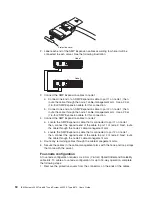
Label
each
end
of
the
SMP
Expansion
cables
according
to
where
it
will
be
connected
to
each
server.
See
the
following
illustration.
Node 2
Node 3
Node 4
Node 1
3.
Connect
the
SMP
Expansion
cables
to
node
1:
a.
Connect
one
end
of
an
SMP
Expansion
cable
to
port
1
on
node
1;
then,
route
the
cable
through
the
node
1
cable-management
arm.
Use
a
2.3-m
(7.6-foot)
SMP
Expansion
cable
for
this
connection.
b.
Connect
one
end
of
an
SMP
Expansion
cable
to
port
2
on
node
1;
then,
route
the
cable
through
the
node
1
cable-management
arm.
Use
a
2.3-m
(7.6-foot)
SMP
Expansion
cable
for
this
connection.
c.
Connect
one
end
of
an
SMP
Expansion
cable
to
port
3
on
node
1;
then,
route
the
cable
through
the
node
1
cable-management
arm.
Use
a
2.3-m
(7.6-foot)
SMP
Expansion
cable
for
this
connection.
4.
Connect
the
SMP
Expansion
cables
to
node
2:
a.
Connect
one
end
of
an
SMP
Expansion
cable
to
port
1
on
node
2;
then,
route
the
cable
through
the
node
2
cable-management
arm.
Use
a
2.3-m
(7.6-foot)
SMP
Expansion
cable
for
this
connection.
Chapter
2.
Installing
options
51
Содержание x3950 8872
Страница 1: ...IBM System x3950 Type 8872 and System x3950 E Type 8874 User s Guide...
Страница 2: ......
Страница 3: ...IBM System x3950 Type 8872 and System x3950 E Type 8874 User s Guide...
Страница 68: ...56 IBM System x3950 Type 8872 and System x3950 E Type 8874 User s Guide...
Страница 98: ...86 IBM System x3950 Type 8872 and System x3950 E Type 8874 User s Guide...
Страница 100: ...88 IBM System x3950 Type 8872 and System x3950 E Type 8874 User s Guide...
Страница 109: ......
Страница 110: ...Part Number 31R1856 Printed in USA 1P P N 31R1856...

