


8.
Carefully
close
the
release
lever
to
secure
the
microprocessor
in
the
socket.
Note:
A
new
heat
sink
comes
in
a
kit
with
a
microprocessor.
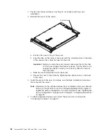
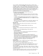
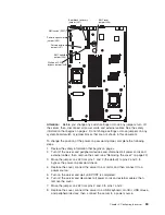
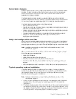
Heat sink
Captive screws
Microprocessor
socket
9.
Install
the
heat
sink.
a.
Remove
the
heat
sink
from
its
package
and
remove
the
cover
from
the
bottom
of
the
heat
sink.
b.
Make
sure
that
the
thermal
material
is
still
on
the
bottom
of
the
heat
sink,
and
position
the
heat
sink
on
top
of
the
microprocessor.
c.
Align
the
captive
screws
on
the
heat
sink
with
the
holes
that
surround
the
microprocessor
socket.
d.
Press
firmly
on
the
captive
screws
and
tighten
them,
alternating
among
the
screws
on
opposite
sides
of
the
heat
sink
until
they
are
tight.
Do
not
overtighten
the
screws
by
using
excessive
force.
10.
Reinstall
the
air
baffle
for
microprocessor
2
(see
step1
on
page
51).
If
you
have
other
devices
to
install
or
remove,
do
so
now.
Otherwise,
go
to
“Completing
the
installation”
on
page
51.
50
System
x3455
Types
7984
and
7986:
User’s
Guide
Содержание x3455 - System - 7984
Страница 1: ...System x3455 Types 7984 and 7986 User s Guide...
Страница 2: ......
Страница 3: ...System x3455 Types 7984 and 7986 User s Guide...
Страница 70: ...56 System x3455 Types 7984 and 7986 User s Guide...
Страница 111: ......
Страница 112: ...Part Number 42D2184 Printed in USA 1P P N 42D2184...


