


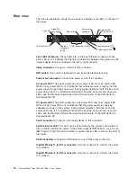
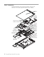
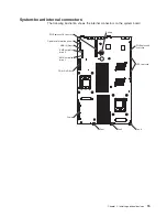
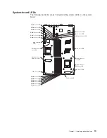


Rear
view
The
following
illustration
shows
the
connectors,
switches,
and
LEDs
on
the
rear
of
the
server.
USB connectors (4)
Ethernet
connectors
(2)
LAN activity LED
Link LED
Video
connector
Power-cord
connector
Serial connector
AC power LED
DC power LED
System locator LED
NMI switch
Link
LEDs
(Ethernet):
These
LEDs
are
on
the
dual
Ethernet
connector.
When
either
LED
is
lit,
it
indicates
that
there
is
an
active
link
between
the
server
and
the
network
device
that
is
connected
to
the
left
or
right
connector.
Video
connector:
Connect
a
monitor
to
this
connector.
NMI
switch:
This
switch
is
reserved
for
use
by
service
technicians
only.
Power-cord
connector:
Connect
the
power
cord
to
this
connector.
AC
power
LED:
The
power
supply
has
an
ac
power
LED
and
a
dc
power
LED.
When
the
ac
power
LED
is
lit,
it
indicates
that
sufficient
power
is
coming
into
the
power
supply
through
the
power
cord.
During
typical
operation,
both
the
ac
and
dc
power
LEDs
are
lit.
For
additional
information
about
the
ac
power
and
dc
power
LEDs,
see
the
Problem
Determination
and
Service
Guide
on
the
IBM
System
x
Documentation
CD.
DC
power
LED:
The
power
supply
has
a
dc
power
LED
and
an
ac
power
LED.
When
the
dc
power
LED
is
lit,
it
indicates
that
the
power
supply
is
supplying
adequate
dc
power
to
the
system.
During
typical
operation,
both
the
ac
and
dc
power
LEDs
are
lit.
For
additional
information
about
the
ac
power
and
dc
power
LEDs,
see
the
Problem
Determination
and
Service
Guide
on
the
IBM
System
x
Documentation
CD.
Serial
connector:
Connect
a
9-pin
serial
device
to
this
connector.
System
locator
LED:
This
LED
can
be
lit
remotely
by
the
system
administrator
to
aid
in
visually
locating
the
server.
If
the
server
supports
IBM
Director,
you
can
use
IBM
Director
to
light
this
LED
remotely.
A
system
locator
LED
is
also
on
the
front
of
the
server.
USB
connectors:
Connect
a
USB
device
to
any
of
these
four
connectors.
Gigabit
Ethernet
1
(LAN
1)
connector:
Use
this
connector
to
connect
the
server
to
a
network.
Gigabit
Ethernet
2
(LAN
2)
connector:
Use
this
connector
to
connect
the
server
to
a
network.
10
System
x3455
Types
7984
and
7986:
User’s
Guide
Содержание x3455 - System - 7984
Страница 1: ...System x3455 Types 7984 and 7986 User s Guide...
Страница 2: ......
Страница 3: ...System x3455 Types 7984 and 7986 User s Guide...
Страница 70: ...56 System x3455 Types 7984 and 7986 User s Guide...
Страница 111: ......
Страница 112: ...Part Number 42D2184 Printed in USA 1P P N 42D2184...


