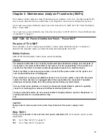
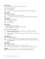
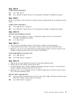
background image

The


following


illustration


shows


the


type


7


power


distribution


bus.


R1

R2

R3

R4

R5

R6

R7

R8

R9

Off

1

2

3

4

5

6

9

7

8


1


Circuit


Breaker


1


6


Circuit


Breaker


in


Tripped


Position


2


Circuit


Breaker


2


7


Circuit


Breaker


Status


Lamp


3


Circuit


Breaker


3


8


Front


of


Power


Distribution


Bus


4


Power


Cord


(Plug


Configuration


May


Vary)


9


Rear


of


Power


Distribution


Bus


5


Circuit


Breaker


in


Normal


Operating


Position


4


7014


Model


T00,


and


Model


T42


Service


Guide

Содержание THINKPAD T42 -

Страница 1: ...7014 Series Model T00 and Model T42 System Rack Service Guide SA38 0577 05 ERserver...

Страница 2: ......

Страница 3: ...7014 Series Model T00 and Model T42 System Rack Service Guide SA38 0577 05 ERserver...

Страница 4: ...nformation Development Department H6DS 905 6C006 11501 Burnet Road Austin Texas 78758 3493 To send comments electronically use this commercial internet address aix6kpub austin ibm com Any information...

Страница 5: ...ack Racks 13 Dimensions 13 Weight 13 Installation Airflow 13 Power Requirements 13 Service Inspection Guide 14 Chapter 2 Maintenance Analysis Procedures MAPs 17 MAP 1520 DC Power Distribution Panel Po...

Страница 6: ...llers 46 Power Distribution Bus 47 Stabilizers 48 Power Distribution Panel Assembly 49 Power Distribution Panel Interior 50 Leveling Feet 51 Model T42 Brace 52 Rack Beacon Assembly 53 Model T42 Kits F...

Страница 7: ...ded to prevent an electrical shock Before installing or removing signal cables ensure that the power cables for the system unit and all attached devices are unplugged When adding or removing any addit...

Страница 8: ...to the requirements of the International Electrotechnical Commission IEC 825 1st edition 1984 and CENELEC EN 60 825 1991 for Class 1 laser products CAUTION A class 1 laser is contained in the device...

Страница 9: ...es or component failures must verify the accuracy of operations performed and data saved or transmitted by the system at or near the time of the outage or failure In addition users must establish proc...

Страница 10: ...viii 7014 Model T00 and Model T42 Service Guide...

Страница 11: ...server pSeries and AIX Information Center at http publib16 boulder ibm com pseries index htm Click hardware documentation Documentation for the AIX operating system is available at the IBM Eserver pSe...

Страница 12: ...v RS 6000 Other company product and service names may be trademarks or service marks of others x 7014 Model T00 and Model T42 Service Guide...

Страница 13: ...tions Types of Power Distribution Power is distributed to the devices and drawers in the rack by ac power distribution buses or by a dc power distribution panel Model T00 only 1 2 4 3 5 1 DC Power Dis...

Страница 14: ...n bus feature codes are 9176 9177 9178 and 7xxx v 9188 7188 power distribution buses have twelve IEC320 C13 200 V to 240 V ac outlets The input ac power to the bus is not switched so each group of two...

Страница 15: ...ng the Rack 7 Outlet for Drawers 4 Outlets for Peripherals Two Facing the Front of the Rack 8 Power Cord Plug Configuration May Vary Note Circuit breakers for Type 7 buses are on the back of the bus T...

Страница 16: ...uit Breaker 1 6 Circuit Breaker in Tripped Position 2 Circuit Breaker 2 7 Circuit Breaker Status Lamp 3 Circuit Breaker 3 8 Front of Power Distribution Bus 4 Power Cord Plug Configuration May Vary 9 R...

Страница 17: ...reaker 1 7a Reset Circuit Breaker 7 2a Reset Circuit Breaker 2 8a Reset Circuit Breaker 8 3a Reset Circuit Breaker 3 9 AC Outlets 4a Reset Circuit Breaker 4 10 AC Outlets Used to Power on Drawers 5a R...

Страница 18: ...tribution bus 1a 2a 5 R1 R2 R3 R4 R5 R6 3a R7 R8 R9 4 1a Circuit Breaker 1 15 Amp 4 AC Power Input 2a Circuit Breaker 2 15 Amp 5 AC Outlets quantity 9 3a Circuit Breaker 3 15 Amp Note The maximum tota...

Страница 19: ...ircuit Breaker 3 20A R7 R8 R9 AC Power Input Type 7 Three Phase Power Distribution Bus Phase 1 Phase 2 Phase 3 Neutral 1a Circuit Breaker 1 20 Amp 6 AC Power Input Phase 1 2a Circuit Breaker 2 20 Amp...

Страница 20: ...bution bus 1a Circuit Breaker 1 20 Amp 1f Circuit Breaker 6 20 Amp 1b Circuit Breaker 2 20 Amp 2 AC Power Input 1c Circuit Breaker 3 20 Amp J1 J12 AC Outlets 1d Circuit Breaker 4 20 Amp 1e Circuit Bre...

Страница 21: ...tified by the Canadian Standards Association CSA These power cords consist of the following v Electrical cables type ST v Attachment plugs complying with National Electrical Manufacturers Association...

Страница 22: ...er distribution panel contains a connection on the rear of the panel for attaching a customer supplied power alarm This alarm is activated when any circuit breaker is tripped or is switched to the off...

Страница 23: ...n each bank of the 48 V dc power distribution panel Thus when one of the 48 V dc power sources fails the devices in the rack still receive power from the other source The exact configuration of the dc...

Страница 24: ...d The 48 V dc rack may be connected to two separate 48 V dc power sources When the rack is connected to two power sources both power sources must be reliably grounded Power cables used in the United S...

Страница 25: ...h side panels 644 mm 25 4 in v T00 EIA units 36 EIA units v T42 EIA units 42 EIA units Weight v T00 Base Empty Rack 244 kg 535 pounds v T00 Full Rack 816 kg 1795 pounds v T42 Base Empty Rack 261 kg 57...

Страница 26: ...rvice the machine Note The correction of any unsafe condition is the responsibility of the owner of the system Do the following checks 1 If the rack is bolted down do the following a Ensure that the r...

Страница 27: ...n place and secure 5 Open the back door of the rack 6 Perform the power off procedure for the power distribution system installed in your rack See Power Off Procedure with the AC Power Distribution Bu...

Страница 28: ...multiple buses c Check for the following conditions for each external device that has an attached power cord v Damage to the power cord v The correct grounded power cord v With the external power cor...

Страница 29: ...the devices that attach to the system It is the responsibility of the customer to ensure that the outlet is correctly wired and grounded to prevent an electrical shock Before installing or removing s...

Страница 30: ...Is the circuit breaker tripped again NO Replace the device power supply Go to MAP 0410 Repair Checkout in the Diagnostic Information for Multiple Bus Systems YES Turn circuit breaker off and replace t...

Страница 31: ...ear cover of the power distribution panel 3 Measure for 40 to 60 V dc on terminal board 2 TB2 between positions one and two side A circuit breaker and between positions five and six side B circuit bre...

Страница 32: ...inal on the circuit breaker 3 Measure for 40 to 60 V dc between the 48 V dc circuit breaker and the return bus bar lower bar in the power distribution panel Is the voltage between 40 and 60 V dc NO Re...

Страница 33: ...ices that attach to the system It is the responsibility of the customer to ensure that the outlet is correctly wired and grounded to prevent an electrical shock Before installing or removing signal ca...

Страница 34: ...p 1522 10 on page 23 Step 1522 3 Was the voltage correct NO Check the customer s outlet for the correct voltage If correct exchange the power cable Then go to Step 1522 10 on page 23 YES Exchange the...

Страница 35: ...1522 10 YES The problem is probably located in the original drawer Go to MAP 1520 DC Power Distribution Panel Power MAP on page 17 in the service guide for the system installed in your rack Step 1522...

Страница 36: ...24 7014 Model T00 and Model T42 Service Guide...

Страница 37: ...device Use one hand when possible to connect or disconnect signal cables to prevent a possible shock from touching two surfaces with different electrical potentials During an electrical storm do not...

Страница 38: ...9188 7188 power distribution buses L1 L1 L1 L1 CB1 CB2 CB3 CB4 CB5 CB6 R6 R5 R4 R3 R2 R1 CB8 CB7 R7 R8 1 2 3 4 5 6 7 8 1 Rear View of the Rack 5 Reset Buttons Two Facing the Front of the Rack 2 Power...

Страница 39: ...are connected to the ac power distribution bus that you are servicing 5 Unplug all the drawer or device power cables from the ac power distribution bus that you are servicing 6 Unplug the power cable...

Страница 40: ...for 40 V dc to 60 V dc between position 5 and position 6 on terminal board 2 to test the power for side B The following illustration shows the front view of the power distribution panel PDP 2 3 1 A1 B...

Страница 41: ...cuit breakers to the off position down CAUTION Energy hazard remove power before servicing Disconnect two power supply cords C23 Note Because a large number of external devices can be connected to the...

Страница 42: ...oval This section covers the removal procedure of the ac power distribution bus 1 Follow the Power Off Procedure with the AC Power Distribution Bus on page 27 2 Turn off power and disconnect the ac po...

Страница 43: ...removal and replacement procedure for the dc power distribution panel CAUTION Energy hazard remove power before servicing Disconnect two power supply cords C23 Removal This section covers the removal...

Страница 44: ...two 48 V dc bus bars and the two 48 V dc return bus bars 8 Ensure that the customer s service provider completely disconnects the two 48 V dc power source cables from the 48 V dc bus bars and the two...

Страница 45: ...e top of the rack and remove the panel 5 4 3 2 1 1 Ground Wire with Connector 4 Ground Wire Connector 2 Mounting Screw quantity 4 5 Mounting Screw This screw secures both the Power Distribution Panel...

Страница 46: ...sure that the customer s dc power source is turned off 7 Ensure that the customer s service provider properly connects the two 48 V dc power source cables to the 48 V dc bus bars and the two 48 V dc...

Страница 47: ...4 Shield 2 Cable Channel Cover 5 Power Distribution Panel PDP 3 Mounting Screw quantity 6 6 Front of Rack 11 Have the customer turn on the 48 V dc power source 12 Follow the steps in Power On Procedu...

Страница 48: ...customer s 48 V dc source power is turned off ensure that a tag or label is positioned over the power source switches to indicate that the power is intended to be off lock out tag out 4 Remove the six...

Страница 49: ...e wire that is attached to the bottom of the circuit breaker 10 Disconnect the mounting nut that attaches the rear of the circuit breaker to the dc power bus bar 13 12 14 4 7 3 10 2 8 6 9 11 1 5 1 A 4...

Страница 50: ...ar of the circuit breaker to the dc power distribution panel with the mounting nut 3 Connect the 48 V dc cable to the circuit breaker using the cable connector nut 4 Connect the two wires to the two c...

Страница 51: ...cket to the rack 4 If necessary also remove the latch plate by removing the mounting screws that attach the plate to the rack Replacement This section covers the replacement procedure for the front or...

Страница 52: ...ack s To relocate a rack refer to step by step instructions described in the 7014 Series Model T00 and Model T42 System Rack Installation Guide order number SA38 0614 40 7014 Model T00 and Model T42 S...

Страница 53: ...4 Series Model T00 and T42 rack Covers 3 10 2 4 5 6 7 1 12 11 7 8 11 Table 1 Frames Side Panels and Top Cover Index Number FRU Part Number Units Per Assembly Description 1 05N4868 1 Frame T00 black 1...

Страница 54: ...High Perforation front door for 1 8M racks black 45P1429 1 T42 High Perforation front door for 2M racks black Note See Table 4 for Mounting Hardware for the following 21P4049 1 T00 100 mm 21P4729 1 T...

Страница 55: ...te 20 mm 11P0723 1 T42 with foam round white 20 mm 21P4468 1 T00 with foam hex black 20 mm 21P4467 1 T42 with foam hex black 20 mm Table 6 Mounting Hardware for Rear Door Index Number FRU Part Number...

Страница 56: ...you will need to request it when placing the order along with the 21L4296 FRU part number 1a 21L4277 1 Top Cable Access Cover Black 1a 21L4290 1 Top Cable Access Cover White 2 31L7536 2 Top Frame Sid...

Страница 57: ...race 1 2 3 4 5 Index Number FRU Part Number Units Per Assembly Description 1 05N4697 1 Earthquake brace kit 2 2 Hinge 3 1 Spacer 4 7 Screw 5 76X4687 1 Bolt Shown for reference only Chapter 4 Parts Inf...

Страница 58: ...needed 1U Filler snap white 2 97H9755 As needed 3U Filler snap black 62X3444 As needed 3U Filler snap white 3 12J4072 As needed 4 12J4073 As needed 3U Filler screw black 5 74F1823 2 Item3 M5 Nut clip...

Страница 59: ...pe 6 power distribution panel 2 3 phase 00P2202 1 Type 6 power distribution panel 3 phase 00P22023 1 Type 6 power distribution panel 1 Phase World Trade 00P3663 1 Type 7 Power distribution panel 1 Pha...

Страница 60: ...s be removed and added to the FRU 2 1624779 4 Nut Clip 3 74F1823 4 Screw Note For information on type 6 and type 7 power distribution buses see AC Power Distribution Bus on page 2 Stabilizers 1 2 3 4...

Страница 61: ...it Shown for reference only Screws are included in the stabilizer kits Power Distribution Panel Assembly 2 1 3 4 5 6 Index Number FRU Part Number Units Per Assembly Description 1 1621191 6 Screw M4 x...

Страница 62: ...20 Amp Circuit Breaker 93H6391 varies 30 Amp Circuit Breaker 8185537 varies 50 Amp Circuit Breaker Shown for reference only Power Distribution Panel Interior Index Number FRU Part Number Units Per As...

Страница 63: ...Leveling Feet 1 1 1 1 2 2 2 2 3 Index Number FRU Part Number Units Per Assembly Description 1 4 Jam nut 2 4 Leveling Feet 3 31L8313 1 Wrench Shown for reference only Chapter 4 Parts Information 51...

Страница 64: ...Model T42 Brace 1 1 2 2 Rear of Rack Index Number FRU Part Number Units Per Assembly Description 1 12K0489 2 Brace 2 4 Bolt Shown for reference only 52 7014 Model T00 and Model T42 Service Guide...

Страница 65: ...er Assembly Description 1 53P1775 1 Cover 2 53P1774 1 Power Supply 3 53P2231 1 Junction Box Assembly 4 53P1776 2 Arm 5 53P3997 1 Card Assembly 6 53P1777 1 Lens 7 53P2236 1 Cable Not Shown 53P2237 Vari...

Страница 66: ...6 11P0463 1 Trim decorative black T42 only 7 11P0489 1 Trim decorative white T42 only 8 31L8305 2 Stabilizer black 9 31L8306 2 Stabilizer white 10 05N4697 1 Earthquake brace 11 31L8302 1 Attachment b...

Страница 67: ...se Chicago Illinois U S A 1 11F0115 1 AFE type 12 plug L6 30P twist lock connector 14 foot cord 30 A single phase Afghanistan Argentina Aruba Bahamas Bangladesh Barbados Belize Bermuda Bolivia Bonnair...

Страница 68: ...249 1 Linecord PDU to wall 14 foot 200 240V 24A UTG0247 PT 40 64P1250 1 Linecord PDU to wall 14 foot 200 240V 24A UTG0247 IEC309 32A P N G 64P1251 1 Linecord PDU to wall 14 foot 200 240V 24A UTG0247 P...

Страница 69: ...Index Number FRU Part Number Units Per Assembly Country or Region 3 11F0107 1 30 A single phase PDL connector Wilco WP type PDL plug 14 foot cord Australia Chapter 4 Parts Information 57...

Страница 70: ...uyana Haiti Hungary Iceland India Iran Iraq Ireland Italy Ivory Coast Jordan Kazakhstan Kenya Kirhizia Kuwait Lesotho Lebanon Liberia Libya Luxembourg Macao S A R of China Macedonia Malawi Mali Malta...

Страница 71: ...tria Czech Republic Denmark Estonia Finland Israel Latvia Liechtenstein Lithuania Netherlands Norway Pakistan Portugal Russia South Africa Sweden Turkey 5 88G4764 1 16 A 3 phase five pin connector IEC...

Страница 72: ...60 7014 Model T00 and Model T42 Service Guide...

Страница 73: ...g to applicable regulations IBM offers product return programs in several countries For country specific instructions refer to the following web site http www ibm com ibm environment products prp phtm...

Страница 74: ...icehandboek voor informatie over de batterij De batterij moet correct worden gerecycled of weggegooid Mogelijk zijn er in uw regio geen K CA inzamelingspunten Meer informatie over het verwerken van ge...

Страница 75: ...l manuale di assistenza per informazioni specifiche sulla batteria La batteria deve essere appropriatamente riciclata o smaltita Il servizio per il riciclaggio potrebbero non essere disponibile nella...

Страница 76: ...teriinformation finns I anv ndar eller servicehandboken Batteriet m ste l mnas till tervinning eller kastas p ett milj s kert s tt Det kanske inte finns n gra tervinningsm jligheter d r du bor N r det...

Страница 77: ...he IBM part number listed on the battery available prior to your call Environmental Design The environmental efforts that have gone into the design of this system signify IBM s commitment to improve t...

Страница 78: ...A Der Ger uschpegel der Einheit ist kleiner oder gleich 70 db A Declared Acoustical Noise Emissions There is no declared acoustical noise emission for the system rack The declared acoustical noise em...

Страница 79: ...untry where such provisions are inconsistent with local law THIS MANUAL IS PROVIDED AS IS WITHOUT WARRANTY OF ANY KIND EITHER EXPRESSED OR IMPLIED INCLUDING BUT NOT LIMITED TO THE IMPLIED WARRANTIES O...

Страница 80: ...68 7014 Model T00 and Model T42 Service Guide...

Страница 81: ...arthquake brace 45 emissions noise 66 external ac power cables 9 F front or rear door removal and replacement 39 H highlighting ix I information accessing ix K kits 54 L laser vi laser compliance stat...

Страница 82: ...ruptible power source 9 related publications ix removal and replacement procedures 25 operating system shutdown 25 power off procedure with ac power distribution bus 27 power off procedure with dc pow...

Страница 83: ...ook is Very Satisfied Satisfied Neutral Dissatisfied Very Dissatisfied Accurate h h h h h Complete h h h h h Easy to find h h h h h Easy to understand h h h h h Well organized h h h h h Applicable to...

Страница 84: ...S 905 6C006 11501 Burnet Road Austin TX 78758 3493 _ _ _ _ _ _ _ _ _ _ _ _ _ _ _ _ _ _ _ _ _ _ _ _ _ _ _ _ _ _ _ _ _ _ _ _ _ _ _ _ _ _ _ _ _ _ _ _ _ _ _ _ _ _ _ _ _ _ _ _ _ _ _ _ _ _ _ _ _ _ _ _ _ _ _...

Страница 85: ......

Страница 86: ...Printed in USA November 2003 SA38 0577 05...

Отзывы: