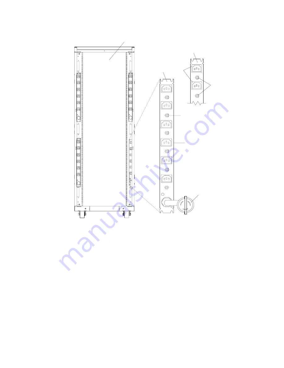
The
following
illustration
shows
the
type
6
power
distribution
bus.
L1
L1
L1
L1
CB1
CB2
CB3
CB4
CB5
CB6
R6
R5
R4
R3
R2
R1
CB8
CB7
R7
R8
1
2
3
4
5
6
7
8
1
Rear
View
of
the
Rack
5
Reset
Buttons
(Two
Facing
the
Front
of
the
Rack)
2
Power
Distribution
Bus
6
Reset
Buttons
3
View
of
the
Power
Distribution
Bus
(Facing
the
Rack)
7
Outlet
for
Drawers
4
Outlets
for
Peripherals
(Two
Facing
the
Front
of
the
Rack)
8
Power
Cord
(Plug
Configuration
May
Vary)
Note:
Circuit
breakers
for
Type
7
buses
are
on
the
back
of
the
bus.
To
access
the
circuit
breaker,
remove
the
side
cover
or
remove
the
bus.
For
information
about
removing
the
side
cover,
refer
to
″
Step
6.
Installing
Multiple
Racks
″
.
For
information
about
removing
the
bus,
refer
to
“Removal
and
Replacement
of
the
AC
Power
Distribution
Bus”
on
page
29.
Chapter
1.
Reference
Information
3
Содержание THINKPAD T42 -
Страница 1: ...7014 Series Model T00 and Model T42 System Rack Service Guide SA38 0577 05 ERserver...
Страница 2: ......
Страница 3: ...7014 Series Model T00 and Model T42 System Rack Service Guide SA38 0577 05 ERserver...
Страница 10: ...viii 7014 Model T00 and Model T42 Service Guide...
Страница 36: ...24 7014 Model T00 and Model T42 Service Guide...
Страница 72: ...60 7014 Model T00 and Model T42 Service Guide...
Страница 80: ...68 7014 Model T00 and Model T42 Service Guide...
Страница 85: ......
Страница 86: ...Printed in USA November 2003 SA38 0577 05...


![Lenovo 90B6 [H50-50 ES] User Manual preview](http://thumbs.mh-extra.com/thumbs/lenovo/90b6-h50-50-es/90b6-h50-50-es_user-manual_201023-01.webp)


