


Chapter
1.
Locations
This
chapter
provides
illustrations
to
help
locate
the
various
connectors,
controls
and
components
of
the
computer.
To
remove
the
computer
cover,
see
“Removing
the
cover”
on
page
5.
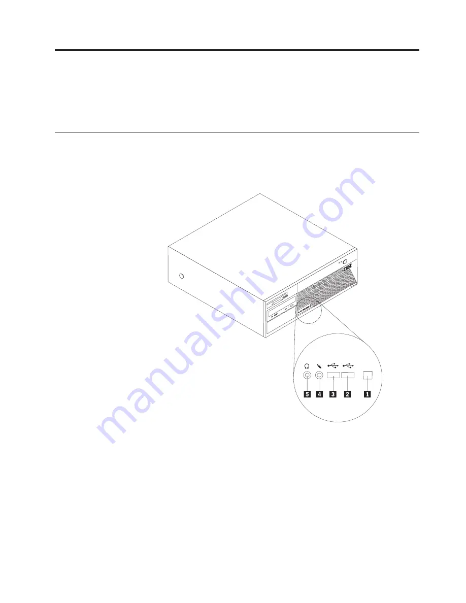
Locating
the
connectors
on
the
front
of
your
computer
The
following
illustration
shows
the
location
of
connectors
on
the
front
of
the
computer.
Note:
Not
all
computer
models
will
have
the
following
connectors.
ThinkCentre
1
3
9
4
1
IEEE
1394
connector
4
Microphone
connector
2
USB
connector
5
Headphone
connector
3
USB
connector
©
Copyright
IBM
Corp.
2005
1
Содержание ThinkCentre 8129
Страница 1: ...ThinkCentre Hardware Replacement Guide Types 8129 8132 8133 Types 8134 8135 8136 ThinkCentre...
Страница 2: ......
Страница 3: ...ThinkCentre Hardware Replacement Guide Types 8129 8132 8133 Types 8134 8135 8136...
Страница 6: ...iv Hardware Replacement Guide...
Страница 35: ......
Страница 36: ...Part Number 39J7755 Printed in USA 1P P N 39J7755...


