


6.
Place
the
failing
system
board
next
to
the
new
system
board
on
a
clean,
flat
surface.
7.
Remove
all
memory
modules
from
the
failing
system
board
and
install
them
in
the
same
location
on
the
new
system
board.
See
“Replacing
memory
modules”
on
page
20.
Return
here
after
installing
the
memory
modules.
8.
Remove
the
microprocessor
from
the
failing
system
board
and
install
it
on
the
new
system
board.
See
“Replacing
the
microprocessor”
on
page
11.
Return
here
after
replacing
the
microprocessor.
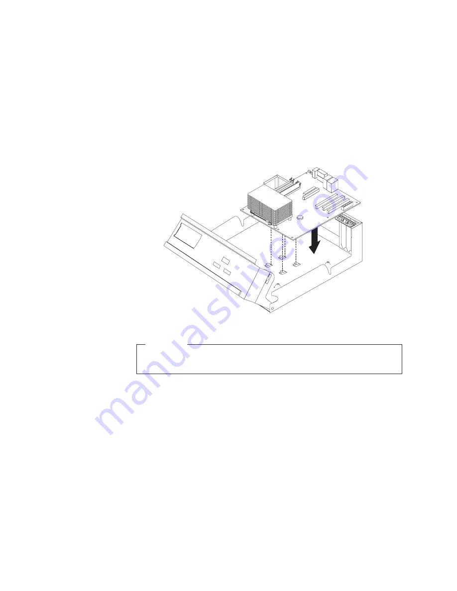
9.
Install
the
new
system
board
by
aligning
the
slots
in
the
metal
plate
on
the
bottom
of
the
system
board
with
the
tabs
on
the
chassis,
then
slide
the
system
board
toward
the
rear
of
the
computer
until
the
screw
holes
are
aligned
properly.
* XXXXXXXXX*
* XXXXXXXXX*
Important
If
the
metal
plate
is
not
aligned
correctly
when
you
install
the
screws,
you
might
damage
the
system
board.
10.
Install
the
seven
screws
that
secure
the
system
board
to
the
chassis.
11.
Reconnect
all
cables
that
were
disconnected
from
the
system
board.
See
“Identifying
parts
on
the
system
board”
on
page
3.
12.
Replace
any
PCI
adapters
that
were
removed.
See
“Replacing
a
PCI
adapter”
on
page
21.
13.
Go
to
“Completing
the
parts
replacement”
on
page
25.
10
Hardware
Replacement
Guide
Содержание ThinkCentre 8129
Страница 1: ...ThinkCentre Hardware Replacement Guide Types 8129 8132 8133 Types 8134 8135 8136 ThinkCentre...
Страница 2: ......
Страница 3: ...ThinkCentre Hardware Replacement Guide Types 8129 8132 8133 Types 8134 8135 8136...
Страница 6: ...iv Hardware Replacement Guide...
Страница 35: ......
Страница 36: ...Part Number 39J7755 Printed in USA 1P P N 39J7755...


