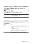
v
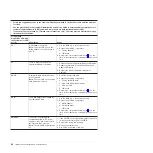
Follow
the
suggested
actions
in
the
order
in
which
they
are
listed
in
the
Action
column
until
the
problem
is
solved.
v
See
the
parts
listing
in
the
Problem
Determination
and
Service
Guide
to
determine
which
components
are
customer
replaceable
units
(CRU)
and
which
components
are
field
replaceable
units
(FRU).
v
If
an
action
step
is
preceded
by
“(Trained
service
technician
only),”
that
step
must
be
performed
only
by
a
trained
service
technician.
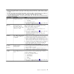
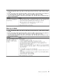
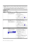
Lit
light
path
diagnostics
LED
with
the
system-error
LED
also
lit
Description
Action
VRM
A
VRM
has
failed
or
is
missing.
1.
Check
the
BMC
log
or
the
system-error
log
to
determine
the
reason
for
the
lit
LED
(for
a
VRM).
2.
Find
the
failing
or
missing
VRM
by
checking
the
LEDs
on
the
microprocessor
tray.
3.
Install
any
missing
VRMs.
4.
Reseat
the
following
components:
a.
Failing
VRM
b.
(Trained
service
technician
only)
Microprocessor
associated
with
the
VRM
c.
Microprocessor
tray
5.
Replace
the
following
components
one
at
a
time,
in
the
order
shown,
restarting
the
server
each
time.
a.
Failing
VRM
b.
(Trained
service
technician
only)
Microprocessor
associated
with
the
VRM
c.
(Trained
service
technician
only)
Microprocessor
tray
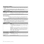
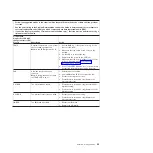
LOG
Information
is
present
in
the
BMC
log
and
system-error
log.
One
or
both
logs
may
be
full
or
close
to
full.
1.
The
system-error
log
is
75%
full;
save
the
log
if
necessary
and
clear
it.
2.
Check
the
log
for
possible
errors.
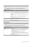
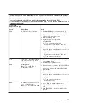
MEM
Memory
failure.
Note:
The
error
LED
on
the
memory
card
is
also
lit.
1.
Remove
the
memory
card
with
the
lit
error
LED
on
the
top
of
the
card;
then,
press
the
light
path
button
on
the
memory
card
to
identify
the
failed
card
or
DIMM.
2.
Reseat
the
DIMM.
3.
Replace
the
following
components
one
at
a
time,
in
the
order
shown,
restarting
the
server
each
time.
a.
Memory
board
b.
DIMM
c.
(Trained
service
technician
only)
Microprocessor
tray
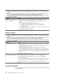
NMI
A
hardware
error
has
been
reported
to
the
operating
system.
Note:
The
PCI
or
MEM
LED
might
also
be
lit.
1.
See
the
BMC
log
and
the
system-error
log.
2.
If
the
PCI
LED
is
lit,
follow
the
instructions
for
that
LED.
3.
If
the
MEM
LED
is
lit,
follow
the
instructions
for
that
LED.
4.
Restart
the
server.
Chapter
6.
Solving
problems
63
Содержание System x3850
Страница 3: ...IBM System x3850 Type 8864 Installation Guide...
Страница 18: ...6 IBM System x3850 Type 8864 Installation Guide...
Страница 42: ...30 IBM System x3850 Type 8864 Installation Guide...
Страница 58: ...46 IBM System x3850 Type 8864 Installation Guide...
Страница 60: ...48 IBM System x3850 Type 8864 Installation Guide...
Страница 78: ...66 IBM System x3850 Type 8864 Installation Guide...
Страница 90: ...78 IBM System x3850 Type 8864 Installation Guide...
Страница 91: ......
Страница 92: ...Part Number 31R1882 Printed in USA 1P P N 31R1882...


