3.6
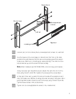
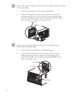
At the front of the rack, using four black hex-head M5 screws in the H3
and H7 holes, secure the system unit to the rack by threading the screws
through the system unit bracket and the rack frame rail into the threaded
rail nuts. Tighten the screws using the 7mm nut driver. Refer to the figure
below step 2.6 on page 6.
3.9
Replace the front bezel of the N7700/N7900 gateway by snapping it
back onto the system unit chassis.
3.5
The system unit is installed from the front of the rack. Position the pallet
near the front of the rack. Lift the system unit using the handles on the
chassis and place the system unit onto the rails. Then slide it into the rack
until the front mounting bracket of the system unit is flush with the frame
rails of the rack.
3.7
Replace the two power supplies at the rear of the gateway system unit by
performing the following steps:
1.
Align the edges of the power supply with the opening in the
system chassis and gently push the power supply into the
chassis until the cam handle begins to rise.
2.
Push the cam handle to the closed position.
3.
Tighten the two thumbscrews on the power supply.
Replace the five fan modules at the front of the system unit by performing
the following steps:
1.
Align the fan with the fan opening in the chassis, and gently
slide it into the chassis as far as it can go.
The fan modules are keyed and can only be installed one
way. If the fan module does not fit properly, flip the module 180
degrees and reinstall it.
2.
Finish seating the fan by pushing firmly on the edges of the
fan housing. When properly seated, the locking tab engages
the handle.
3.
Tighten the thumbscrew on the handle.
Note:
The upper two fan modules are installed
with the handles at the bottom, and the lower three fan modules
are installed rotated 180 degrees, with the handles at the top.
3.8
9
Содержание System Storage N7000
Страница 1: ...N7000 Series Gateway Installation and Setup Instructions IBM System Storage...
Страница 2: ......
Страница 4: ......


