background image


 Installation

1. Measure the customer's primary power using the

 3745-130/150/160/170/17A

and 3746-900 Installation Guide, SY33-2067, Chapter 2 "Measuring the Cus-
tomer's Primary Power", steps 1 through 3.

The acceptable voltage limits are: 90 through 127 volts. See “Input Voltages”
on page 1-7.

2. Ensure that the 3745 is not connected to the customer's power supply

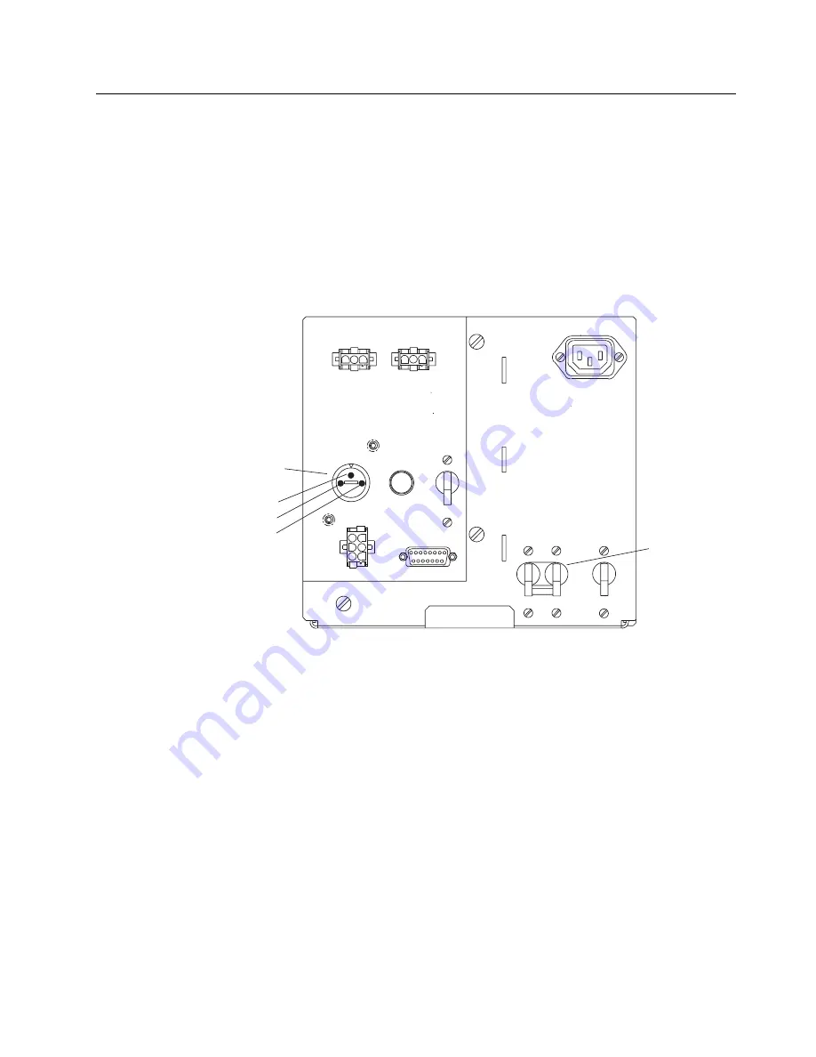
Ensure that CB1 is switched to OFF on the front of the 3745 primary power box
(see Figure 1-3 for location).

Voltage
Selection
Switch

220
200
240

J6

J7

J9

J8

F1

SW1

Main Line CB

CB1

CP2

CP3

J1

Figure

1-3. Primary Power Box (Front View)

On the front side of the primary power box, set the SW1 switch (see Figure 1-3
for location) to position 240.

3. If the machine is shipped with the 200/240-volts line cord installed, it must be

disconnected and removed.

a. Remove the clamp securing the power cord. Keep this clamp and its screw

for further use.

b. Disconnect the power cord from connector J3 (see Figure 1-4 on page 1-6

for location).


Chapter 1. Generalities

1-5

Содержание RPQ 7L1184

Страница 1: ...3745 Communication Controller Models 130 150 160 170 and 17A 3746 Expansion Unit Model 900 IBM 100 120 Volt Connection RPQ 7L1184 Installation and Maintenance Information SY33 2078 3...

Страница 2: ......

Страница 3: ...3745 Communication Controller Models 130 150 160 170 and 17A 3746 Expansion Unit Model 900 IBM 100 120 Volt Connection RPQ 7L1184 Installation and Maintenance Information SY33 2078 3...

Страница 4: ...readers comments appears at the back of this publication If the form has been removed address your comments to International Business Machines Corporation Department 6R1LG 180 Kost Road Mechanicsburg...

Страница 5: ...tion 1 1 Specifications 1 2 Dimensions 1 2 Service Clearances 1 2 Weight 1 2 Heat Output 1 2 Airflow 1 2 Power Requirements 1 2 Environment Operating 1 2 Plan View 1 3 Component Location 1 4 Installat...

Страница 6: ...iv RPQ 7L1184...

Страница 7: ...uant to Part 15 of the FCC Rules These limits are designed to provide reasonable protection against harmful interference when the equipment is operated in a commercial environment This equipment gener...

Страница 8: ...vi RPQ 7L1184...

Страница 9: ...assembly The areas checked by this procedure are 1 Input power voltage 2 Circuit protector 3 Safety label 4 Power supply part number 5 Grounding 6 Covers Important Note The transformer assembly is a...

Страница 10: ...mer Assembly Part Number on page 1 8 Step 5 Grounding Check that electrical continuity is assured between the ground wires of the power cords and between those ground wires and the frame ground Step 6...

Страница 11: ...Expansion Unit Model 900 to a customer s 100 120 volt power supply It consists of a transformer with an input power cord with a plug and an output power cord Overload protection is provided through a...

Страница 12: ...37 25 lb Heat Output 50 W Airflow Convection only Power Requirements kVA 1 2 Phase 1 Input Current 11 A maximum for United States Canada 13 A maximum for Japan Inrush current 180 A maximum Branch circ...

Страница 13: ...Plan View Metric scale 1 mm 5 mm Measurements in inches are shown in parentheses 1 A floor cutout is required for raised floor installation Figure 1 1 Plan View Chapter 1 Generalities 1 3...

Страница 14: ...D e t a i l B N E P A S O U V R I R D O N O T O P E N 2 4 0 V D e t a i l B O u t p u t C o r d 2 I E C P l u g D O N O T O P E N S a f e t y l a b e l S e e D e t a i l C U S A a n d C A N A D A D e...

Страница 15: ...nt of the 3745 primary power box see Figure 1 3 for location Voltage Selection Switch 220 200 240 J6 J7 J9 J8 F1 SW1 Main Line CB CB1 CP2 CP3 J1 Figure 1 3 Primary Power Box Front View On the front si...

Страница 16: ...former to connector J3 Secure the cable with the clamp and screw removed in step 3a 6 Route the input power cord to the customer s receptacle and insert the power plug into the customer s main socket...

Страница 17: ...nge check if the circuit protector is in the ON position For part number assembly refer to Transformer Assembly Part Number on page 1 8 AC Voltage Limits Input Voltages Voltages Canada Japan U S A Nom...

Страница 18: ...F1232 7 46 3 57 18 14 U S A CANADA non locking plug 34F1233 4 46 3 57 18 14 U S A CANADA moisture resistant plug 34F1234 51 46 3 57 18 14 JAPAN locking plug 34F1235 2 1 3 2 72 51 1 6 JAPAN non locking...

Страница 19: ...ormation Publication No SY33 2078 3 Please send us your comments concerning this book We will greatly appreciate them and will consider them for later releases of the present book If you prefer sendin...

Страница 20: ...s We d Like to Hear from You SY33 2078 3 IBM Fold and Tape Please do not staple Fold and Tape PLACE POSTAGE STAMP HERE IBM France Centre d Etudes et Recherches Service 0798 BP 79 06610 La Gaude France...

Страница 21: ......

Страница 22: ...IBM Part Number 26F1485 Printed in U S A 26F1485 SY33 2 78 3...

Отзывы: