background image

8.

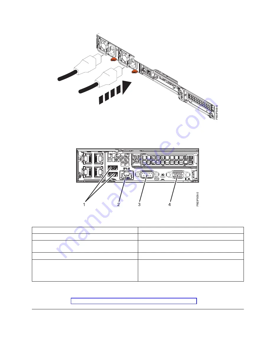
Attach all cables to the rear of the server.

Table 1. Input and output ports

Identifier

Description

1

USB 2.0 used for keyboard and mouse

2

Ethernet Intelligent Platform Management Interface
(IPMI)

3

Serial IPMI

4

Video Graphics Array (VGA) used for monitor. Only the
1024 x 768 at 60 Hz VGA setting is supported. Only up
to a 3-meter cable is supported. Text based capability is
only supported at this time.

9.

Plug the system power cords and the power cords for any other attached devices into the alternating
current (AC) power source.

10.

Continue with Configuring the HMC by using the HMC E interface.

Installing the HMC into the rack using the slide rails

If you are installing the HMC into the rack using the slide rails, complete the following tasks.

Figure 2. Plugging the power cords into the power supplies

Figure 3. Rear ports

Installing the 7063-CR1 into a rack

5

Содержание Power Systems 7063-CR1

Страница 1: ...Installing the 7063 CR1 into a rack IBM...

Страница 2: ...ii Installing the 7063 CR1 into a rack...

Страница 3: ...7063 CR1 system 1 Installing the HMC into the rack using the fixed rails 3 Attaching the fixed rails to the system chassis and to the rack 3 Installing the system into the rack and connecting and rou...

Страница 4: ...iv Installing the 7063 CR1 into a rack...

Страница 5: ...tures http www ibm com support knowledgecenter POWER8 p8hbf p8hbf_8xx_kickoff htm Completing inventory for your system Use this information to complete inventory for your system 1 Verify that you rece...

Страница 6: ...w access to the inside of the rack enclosure where you plan to place the unit as shown in Figure 1 4 Determine to place the system in the rack Record the EIA location 5 Facing the front of the rack an...

Страница 7: ...pace Ensure that you have the necessary parts to install the rails The following parts are included with the rail kit v Slide rail screws used to attach the two parts of each slide rail v Slide rail r...

Страница 8: ...e front of the rack rail toward the front of the rack rail flange Align the slide rail pins with the holes in the rail flange and pull them until the rail latch clicks into place f Using a screwdriver...

Страница 9: ...e is supported Text based capability is only supported at this time 9 Plug the system power cords and the power cords for any other attached devices into the alternating current AC power source 10 Con...

Страница 10: ...arrive fully assembled To install the slide rails into the rack you must disassemble the slide rails into four pieces 1 Remove the lower direct access storage device DASD backplane screw on either sid...

Страница 11: ...ng it to the front of the rack and locate the selected EIA unit 5 From the front of the rack insert the pins on the front of the slide rail 1 into the holes on the front of the rack that you previousl...

Страница 12: ...the rack Pull the slide rail toward you to insert the two pins 1 into the rack holes 2 Pull the rail until the rail spring clip 3 clicks into place Install the screw 4 to secure the slide rail to the...

Страница 13: ...m requires two people to install the system into the rack 1 Fully extend the slide rails until the rails click into the service position A 2 Using two people lift the system and align the lower roller...

Страница 14: ...with a green arrow 4 Push the system into the rack 5 Tighten the thumbscrews on either side of the system to secure the system to the rack Figure 9 Aligning the lower roller pins on the chassis rails...

Отзывы: