background image

13

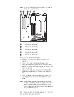
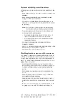
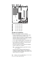
PCI slot 2 32-bit (J32)

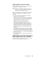
Installing options

55

Содержание Netfinity 5100 8658 1RY

Страница 1: ...Netfinity 5100 Type 8658 Models 11Y 21Y 31Y 41Y 51Y 1RY 2RY 3RY 4RY 5RY S10K 2615 00...

Страница 2: ...al errors Changes are periodically made to the information herein these changes will be incorporated in new editions of the publication IBM may make improvements and or changes in the product s and or...

Страница 3: ...IBM PC Server products Important safety information Be sure to read all caution and danger statements in this book before performing any of the instructions Leia todas as instru es de cuidado e perig...

Страница 4: ...he World Wide Web WWW to download Diagnostic BIOS Flash and Device Driver files File download address is http www us pc ibm com files html IBM Online Addresses The HMM manuals online address is http w...

Страница 5: ...ics table 19 Diagnostic programs and error messages 20 Text messages 20 Starting the diagnostic programs 21 Viewing the test log 22 Diagnostic error message tables 23 Recovering BIOS 23 Troubleshootin...

Страница 6: ...65 Removing the server door tower model 66 Removing the bezel rack or tower 67 Working with adapters 67 Adapter considerations 68 Installing an adapter 69 Installing internal drives 71 Internal drive...

Страница 7: ...er documentation 114 Netfinity Manager system requirements 114 Netfinity Manager for OS 2 system requirements 114 Netfinity Manager for Windows 95 and Windows 98 system requirements 115 Netfinity Mana...

Страница 8: ...Monitor 145 System Partition Access 145 System Profile 146 Update Connector Manager 146 Web Manager Configuration 146 Delaying Netfinity Manager startup on OS 2 systems 146 Getting more information ab...

Страница 9: ...fault messages 183 Undetermined Problems 183 Parts listing Type 8658 185 Keyboards 189 Power cords 189 Related service information 191 Safety information 192 General safety 192 Electrical safety 193 S...

Страница 10: ...x Netfinity 5100 Type 8658 Models 11Y 21Y 31Y 41Y 51Y 1RY 2RY 3RY 4RY 5RY...

Страница 11: ...run the test A failed system might be part of a shared DASD cluster two or more systems sharing the same external storage device s Prior to running diagnostics verify that the failing system is not pa...

Страница 12: ...y POST error messages displayed on the screen If an error is displayed look up the first error in the POST error codes on page 171 v Check the information LED panel System Error LED if on see Informat...

Страница 13: ...erver and on the front under the trim bezel You will need these numbers when you register your server with IBM To register your server go to the following World Wide Web address http www ibm com pc re...

Страница 14: ...0 lb when fully configured Size Tower Model v Height 440 mm 17 3 in v Depth 660 mm 26 0 in v Width 220 mm 8 7 in v Weight approximately 27 22 Kg 60 lb when fully configured Integrated functions v Netf...

Страница 15: ...The unique design of your server takes advantage of advancements in symmetric multiprocessing SMP data storage Your server combines v Impressive performance using an innovative approach to SMP Your s...

Страница 16: ...System Management Processor on the system board This processor in conjunction with the Netfinity Manager provided on your ServerGuide CDs allows you to manage the functions of the server locally and...

Страница 17: ...ces and software applications As always your IBM server meets stringent worldwide certifications for power electromagnetic compatibility EMC and safety Refer to the Safety Information section for addi...

Страница 18: ...ption v Redundant hot swap cooling v Redundant Ethernet capabilities with optional adapter v Vital Product Data VPD on processor complex system board power backplane SCSI backplane and each power supp...

Страница 19: ...5 Cover release latch 6 Reset button 7 Power control button 8 Power control button shield if installed General information 9...

Страница 20: ...Operator Information panel on page 14 for more information Hard Disk Status Light Each of the hot swap drives has a Hard Disk Status light When this amber light is on continuously the drive has failed...

Страница 21: ...AC and DC Power lights are on For any other combination of lights see Power supply LEDs on page 19 Starting the server After you have plugged the power cord of your server into an electrical outlet an...

Страница 22: ...an turn off the server by pressing the Power control button on the front of the server Pressing the Power control button starts an orderly shutdown of the operating system if this feature is supported...

Страница 23: ...Watch for the System Power light on the operator information panel to stop blinking General information 13...

Страница 24: ...ode the system power supply is turned off and AC current is present If this light is not on the power cord is not connected the power supply has failed or this LED has failed POST complete light This...

Страница 25: ...system board will also be on to further isolate the error Ethernet speed Light This green LED lights when the Ethernet LAN speed is 100 Mbps Ethernet Link Status Light This green LED lights when ther...

Страница 26: ...16 Netfinity 5100 Type 8658 Models 11Y 21Y 31Y 41Y 51Y 1RY 2RY 3RY 4RY 5RY...

Страница 27: ...d the table in Information panel system error LED on page 162 for more information v Diagnostic programs and error messages The server diagnostic programs are stored in upgradable read only memory ROM...

Страница 28: ...mall computer system interface messages The table in SCSI error codes on page 178 lists actions to take if you receive a SCSI error message Note If your server does not have a hard disk drive ignore a...

Страница 29: ...the diagnostics panel on the system board See Light path diagnostics table below for information on identifying problems using these LEDs DASD2 DASD1 VRM PCI A PCI B CPU MEM FAN TEMP NMI OVER NON PS3...

Страница 30: ...rmat is as follows fff ttt iii date cc text message where fff is the three digit function code that indicates the function being tested when the error occurred For example function code 089 is for the...

Страница 31: ...tic programs You can press F1 while running the diagnostic programs to obtain Help information You also can press F1 from within a help screen to obtain online documentation from which you can select...

Страница 32: ...e drivers and so on by selecting Hardware Info from the top of the screen When the tests have completed you can view the Test Log by selecting Utility from the top of the screen If the hardware checks...

Страница 33: ...BIOS flash diskette from one of the following sources v Use the ServerGuide program to make a BIOS flash diskette v Download a BIOS flash diskette from the World Wide Web Go to http www pc ibm com sup...

Страница 34: ...erent cable If you set the Ethernet controller to operate at 100 Mbps you must use Category 5 cabling If you directly connect two workstations without a hub or if you are not using a hub with X ports...

Страница 35: ...bps Ethernet controller problems that have definite symptoms Table 1 Ethernet troubleshooting chart Ethernet controller problem Suggested Action The server stops running when loading device drivers Th...

Страница 36: ...workstation v Run diagnostics on the LEDs v The function of this LED can be changed by device driver load parameters If necessary remove any LED parameter settings when you load the device drivers Dat...

Страница 37: ...ver ODI driver and suggested actions to resolve each problem Table 2 Novell NetWare or IntraNetWare ODI driver messages for the Ethernet controller PCNTNW NW 026 The MSM is unable to parse a required...

Страница 38: ...Explanation The driver failed to allocate the memory needed for normal operation Action Add more memory or free some memory resources in the server Then restart the server PCNTNW NW 074 The hardware i...

Страница 39: ...undancy that conflicts with another specified mode Action Make sure that your hardware configuration matches the software settings PCNTNW NW 126 The group bit in the node address override was cleared...

Страница 40: ...oblem persists go to Starting the diagnostic programs on page 21 to run the diagnostic programs PCNTNW NW 180 The DMA parameter is not necessary for PCI device Explanation The Ethernet controller does...

Страница 41: ...registration failed Explanation The NDIS stack is not configured correctly Action Check and correct your configuration PCNTND 15 Device not found Explanation The driver cannot find an Ethernet control...

Страница 42: ...INI file to match the IRQ setting shown in the PCI Slot Device Information selection of the Advanced Setup menu in the Configuration Setup Utility program PCNTND 25 PCI scan specified PCI bus not fou...

Страница 43: ...the primary connection will cause the network traffic to automatically transfer to the primary Ethernet controller PermaNet Server Switching back to Primary Adapter Explanation The primary Ethernet c...

Страница 44: ...fy that the Ethernet controller is enabled If the Ethernet controller is enabled run the diagnostic programs pnt0 13 add_intr_handler failed Interrupts already enabled Explanation The interrupt reques...

Страница 45: ...r hardware settings v Run the NETCONFIG program to search for another Ethernet controller pnt0 22 add_intr_handler failed Out of range IPL Explanation The interrupt request IRQ that was specified or t...

Страница 46: ...ircuits for instance if there is a loose screw causing a short circuit on a circuit board 3 Remove adapters and disconnect the cables and power connectors to all internal and external devices until sy...

Страница 47: ...and accumulators that contain heavy metals must not be disposed of with normal domestic waste They will be taken back free of charge by the manufacturer distributor or representative to be recycled o...

Страница 48: ...ome active 5 Turn on the server 6 Start the Configuration Setup Utility program and set configuration parameters v Set the system date and time v Set the power on password v Reconfigure your server Te...

Страница 49: ...val v Cables for optional adapters are routed according to the instructions provided with the adapters ensure that cables are not restricting air flow v The fans are operating correctly and the air fl...

Страница 50: ...40 Netfinity 5100 Type 8658 Models 11Y 21Y 31Y 41Y 51Y 1RY 2RY 3RY 4RY 5RY...

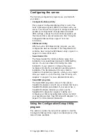
Страница 51: ...gned for IBM Netfinity servers You can use these CDs during the initial installation of your server to configure the server hardware and simplify your network operating system installation The ServerG...

Страница 52: ...p IBM Corporation 1998 F1 Help Move Esc Exit Enter Select System Summary System Information Devices and I O Ports Date and Time System Security Start Options Advanced Setup Error Logs Save Settings Re...

Страница 53: ...elect this choice to set the system date and time and to change the system time sent to the Advanced System Management Processor service processor when the server is started This choice appears only o...

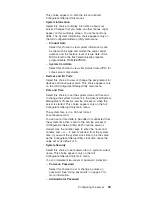
Страница 54: ...teristics such as the keyboard speed You also can specify whether the keyboard number lock starts on or off You also can enable the server to run without a diskette drive monitor or keyboard The serve...

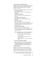
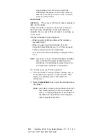
Страница 55: ...t Device Information Select this choice to view and identify system resources used by PCI devices PCI devices automatically communicate with the server configuration information This usually results i...

Страница 56: ...t to enable then use the arrow keys to select Enable v System Service Processor Settings Select this choice to view the interrupt request setting IRQ used by the Configuration Setup Utility system ser...

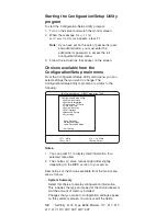
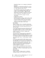
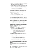
Страница 57: ...main locked until you enter the correct password You can use any combination of up to seven characters A Z a z and 0 9 for your power on password Keep a record of your password in a secure place If yo...

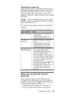
Страница 58: ...s then remove the cover See Removing the cover door and bezel on page 63 3 Change the setting of the password override switch switch 8 on switch block 1 on the system board to ON 4 Install the server...

Страница 59: ...sword to access the Configuration Setup Utility program v All choices are available on the Configuration Setup Utility main menu Administrator and power on password v You can enter either password to...

Страница 60: ...use the configuration method supplied with the RAID adapter to view or change SCSI settings for attached devices Starting the SCSISelect utility program To start the SCSISelect utility program 1 Turn...

Страница 61: ...gure SCSI device parameters Before you can make updates you must know the ID of the device whose parameters you want to configure Note The Maximum Sync Transfer Rate represents the transfer rate for U...

Страница 62: ...on the hard disk drive As a last resort before replacing a failing hard disk drive Note If your server has a PCI RAID adapter installed refer to the RAID adapter documentation for instructions for per...

Страница 63: ...or remove the component while the system is running provided that your system is configured to support this function For complete information about installing or removing a hot swap component see the...

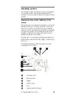
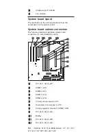
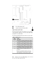
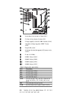
Страница 64: ...on identifies system board connectors for user installable options 1 PCI slot 1 32 bit J27 2 DIMM 1 J23 3 DIMM 2 J21 4 DIMM 3 J19 5 DIMM 4 J18 6 Primary microprocessor U3 7 Secondary microprocessor U1...

Страница 65: ...13 PCI slot 2 32 bit J32 Installing options 55...

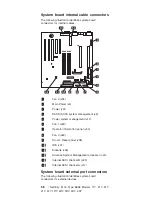
Страница 66: ...nt J12 6 Fan 1 J59 7 Operator information panel J50 8 Fan 2 J60 9 On off Reset panel J38 10 IDE J31 11 Diskette J26 12 Advance System Management processor J40 13 Internal SCSI channel B J29 14 Interna...

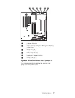
Страница 67: ...nagement Process or port J13 3 USB ports J11 4 Ethernet ports J9 5 Keyboard mouse port J6 6 Serial ports J3 System board switches and jumpers The following illustration identifies the switches and jum...

Страница 68: ...4 See Table 8 on page 59 for specific settings 2 Microprocessor speed setting requires switches 1 4 See Table 8 on page 59 for specific settings 3 Microprocessor speed setting requires switches 1 4 Se...

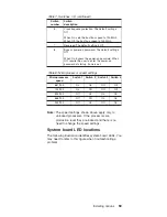
Страница 69: ...word at startup if one is set Table 8 Microprocessor speed settings Microprocessor speed Switch 1 Switch 2 Switch 3 Switch 4 667 133 On On Off Off 733 133 On Off Off Off 800 133 Off On On On 866 133 O...

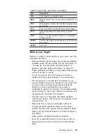
Страница 70: ...DIMM2 failure CR28 10 DIMM3 failure CR18 11 DIMM4 failure CR20 Table 9 Diagnostics panel LEDs LED Description PS1 Power supply 1 failure PS2 Power supply 2 failure PS3 Power supply 3 failure NON Non r...

Страница 71: ...y while working with your server or options v You do not need to turn off the server to install or replace hot swap power supplies or hot swap drives v The orange color on components and labels in you...

Страница 72: ...ers are routed according to the instructions provided with the adapters v A failed fan is replaced within 48 hours Working inside a server with power on Your server is designed to operate safely while...

Страница 73: ...osed circuitry v Prevent others from touching components v When you are installing a new option touch the static protective package containing the option to a metal expansion slot screw or other unpai...

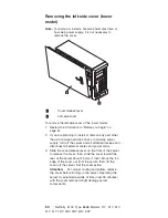
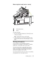
Страница 74: ...the server and all attached devices and disconnect all external cables and power cords 3 Slide the cover release lever on the front of the server to release the cover then slide the cover toward the...

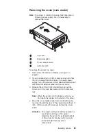
Страница 75: ...s and disconnect all external cables and power cords 3 Release the left and right side latches and pull the server out of the rack enclosure until both slide rails lock Note When the server is in the...

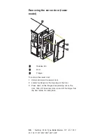
Страница 76: ...Unlock and open the server door 2 Locate the flange on the top edge of the door 3 Press down on the flange while pressing out on the door then lift the server door up and off the hinge Set the door as...

Страница 77: ...a safe place Working with adapters You can install up to five peripheral component interconnect PCI adapters in the expansion connectors called slots on the system board of your server Your server com...

Страница 78: ...v You can install full length adapters in all expansion slots v You can install a 32 bit adapter in any of the PCI slots but you might want to install it in a 32 bit slot and use the 64 bit slots for...

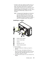
Страница 79: ...ogram select Start Options from the main menu then select the PCI SCSI adapter boot option See Configuring the server on page 41 for details on using the Configuration Setup Utility program Installing...

Страница 80: ...ive surface 8 Set any jumpers or switches as described by the adapter manufacturer 9 Install the adapter a If necessary open the adapter support bracket retaining flap b Carefully grasp the adapter by...

Страница 81: ...ives allow your system to read multiple types of media and store more data Several types of drives are available such as v Diskette already installed v Hard disk v CD ROM already installed v Tape incl...

Страница 82: ...activity light 4 Hard disk status light 5 SCSI ID 2 6 SCSI ID 3 7 SCSI ID 4 8 SCSI ID 8 9 SCSI ID 9 10 Hot swap bays 11 Non hot swap bay C 12 Non hot swap bay B 13 Non hot swap bay A 72 Netfinity 5100...

Страница 83: ...to operate your system while a hard disk drive is removed or installed These drives are known as hot swappable drives They are also referred to as hot swap drives Each hot swap drive that you plan to...

Страница 84: ...th a 50 pin connector in one of the empty non hot swap bays bays A B you need a 68 pin to 50 pin converter To order the converter contact your IBM reseller or IBM marketing representative Note The ser...

Страница 85: ...lled on the drive tray place the drive in the drive tray and being careful not to over tighten the screws attach the drive to the tray using the four screws provided with the option kit 2 Remove the f...

Страница 86: ...ive has failed v When the amber light flashes slowly one flash per second the drive is being rebuilt v When the amber light flashes rapidly three flashes per second the controller is identifying the d...

Страница 87: ...l 2 Slim filler bezel 3 Hard disk drive 4 Drive tray 5 Drive tray handle in open position To replace a drive in a hot swap bay 1 Before you begin do the following v Read the documentation that comes w...

Страница 88: ...l it locks the drive in place 8 Check the hard disk drive status indicators to verify that the hard disk drive is installed properly see Server controls and indicators on page 8 for the location of th...

Страница 89: ...el from the bay opening by pulling the filler panel away from the server You do not need the filler panel when you have a drive installed in the bay 4 Touch the static protective bag containing the dr...

Страница 90: ...CSI cable to the SCSI channel B connector on the system board or to an optional SCSI adapter as appropriate See System board internal cable connectors on page 56 for the location of the SCSI connector...

Страница 91: ...g DIMMs changes the configuration information in the server Therefore after installing or removing a DIMM you must save the new configuration information by using the Configuration Setup Utility progr...

Страница 92: ...exists between the DIMM and the retaining clips the DIMM has not been properly installed In this case open the retaining clips and remove the DIMM then reinsert the DIMM 5 If you have other options to...

Страница 93: ...is the startup processor and the microprocessor with the higher stepping level is the application processor If both microprocessors have the same stepping level the microprocessor installed in microp...

Страница 94: ...from the package b Center the microprocessor over the microprocessor connector and carefully press the microprocessor into the connector Note To remove a microprocessor pull upward on the microproces...

Страница 95: ...s 7 If you have other options to install or remove do so now otherwise go to Installing the cover on page 92 Installing or removing a power supply Your server comes with one power supply You can repla...

Страница 96: ...n this bay it becomes power supply 2 Power supply bay 3 Your server comes with power supply 3 installed AC power LED This light provides status information about the power supply During normal operati...

Страница 97: ...replace the power supply backplane with the power supply backplane option you can add a second and third power supply and the power supplies will be hot swappable After you install a power supply ver...

Страница 98: ...unded electrical outlet 6 Verify that the DC Power light and AC Power light on the power supply are lit indicating that the power supply is operating correctly 7 If you have other options to install o...

Страница 99: ...lose the cable restraint bracket c Unplug the power cord from the electrical outlet d Continue with step 5 4 If you are replacing the power supply a Place the handle on the replacement power supply in...

Страница 100: ...n then slide the power supply into the chassis b Gently close the handle on the power supply to seat the power supply in the bay c Plug the power cord for the power supply into the power cord connecto...

Страница 101: ...mine which fan assembly to replace by checking the LED on each fan a lit LED indicates the fan to replace 4 Remove the fan assembly from the server by pressing the blue release latch for the fan and p...

Страница 102: ...er 1 Align the cover with the left side of the server about 25 mm 1 inch from the front of the server place the bottom of the cover on the bottom rail of the chassis 2 Insert the tabs at the top of th...

Страница 103: ...til the bezel clicks into place To install the server door 1 Set the door on the bottom hinge 2 Press the flange downward while pressing the top of the door toward the server until the flange connects...

Страница 104: ...ver about 25 mm 1 inch from the front of the server the flanges on the left and right sides of the cover should be on the outside of the server chassis 2 Hold the cover against the server and slide th...

Страница 105: ...cting external options If you install a SCSI adapter you can attach a SCSI storage expansion enclosure to your server Installation procedure To attach an external device 1 Read Before you begin on pag...

Страница 106: ...ignments and other details about these connectors see Input Output ports on page 97 1 Advanced System Management Interconnect knockout 2 Parallel 3 Management C 4 Video 5 USB 1 6 USB 2 7 Ethernet 8 Ke...

Страница 107: ...iguration Setup Utility program to configure the parallel port as bidirectional that is so that data can be both read from and written to a device In bidirectional mode the server supports the ECP and...

Страница 108: ...O Data 2 Data 2 5 I O Data 3 Data 3 6 I O Data 4 Data 4 7 I O Data 5 Data 5 8 I O Data 6 Data 6 9 I O Data 7 Data 7 10 I ACK ACK 11 I BUSY WAIT 12 I PE paper end PE paper end 13 I SLCT select SLCT se...

Страница 109: ...Enter Note The Devices and I O Ports choice appears only on the full configuration menu If you set two levels of passwords you must enter the administrator password to access the full configuration m...

Страница 110: ...more than two USB devices you must use a hub to connect the devices The hub provides multiple connectors for attaching additional external USB devices USB technology provides 12 megabits per second Mb...

Страница 111: ...xiliary device port that supports a mouse or other pointing device The following table shows the pin number assignments for the auxiliary device connector on the rear of your server 6 4 2 1 3 5 Table...

Страница 112: ...ltra 160 m SCSI channels both internal Each of these channels supports up to 15 SCSI devices In addition this controller uses v Double transition clocking to achieve high transfer rates v Domain name...

Страница 113: ...st have a unique SCSI ID This ID enables the SCSI controller to identify the device and ensure that different devices on the same SCSI channel do not attempt to transfer data simultaneously SCSI devic...

Страница 114: ...essage 27 Select 61 Select 28 Control Data 62 Control Data 29 Request 63 Request 30 Input Output 64 Input Output 31 Data 8 65 Data 8 32 Data 9 66 Data9 33 Data 10 67 Data 10 34 Data 11 68 Data 11 Ethe...

Страница 115: ...rface card NIC adapter that you can install in your server If you install this NIC adapter and connect it to the same logical segment as the primary Ethernet controller you can configure the server to...

Страница 116: ...OS 2 Windows NT Server and IntraNetWare The setup required for each operating system follows IBM Operating System 2 OS 2 1 Add the redundant NIC adapter according to the instructions that are provide...

Страница 117: ...e order listed 1 IBM Failover DMI Agent 2 IBM PCI Hot Plug Solution 3 IBM Netfinity 10 100 Fault Tolerant Adapter device drivers Note The order of installation is important You must install the IBM Ne...

Страница 118: ...art the machine 4 From the Windows NT Server desktop select Control Panel then select the Network icon then select the Adapters tab 5 Highlight one of the adapters that will be in the redundant pair a...

Страница 119: ...CONDARY y where d and path are the drive and path where the driver is located and x and y are the PCI slot numbers where the redundant pair is located The slot number associated with the integrated Et...

Страница 120: ...connected 4 Not connected 8 Not connected Advanced System Management ports Your server has three communication ports dedicated to the Netfinity Advanced System Management Processor One port uses a sta...

Страница 121: ...les through the cable restraint bracket on the rear of the server 1 Cable restraint bracket 2 Advanced system management Interconnect knockout 3 Parallel 4 Management 5 Video 6 USB 1 7 USB 2 8 Etherne...

Страница 122: ...Additionally for rack models be sure to route the cables through the cable management arm on the rack Cable straps 112 Netfinity 5100 Type 8658 Models 11Y 21Y 31Y 41Y 51Y 1RY 2RY 3RY 4RY 5RY...

Страница 123: ...k v Serial Connection Control Use the Serial Connection Control service to use a Netfinity Manager system modem to establish a connection with any Netfinity Manager system that has a modem Once this c...

Страница 124: ...ion about Netfinity Manager on page 147 Netfinity Manager system requirements The minimum system requirements for Netfinity Manager vary based on which supported operating system is running on your sy...

Страница 125: ...Netfinity Manager is 6 5 MB 9 MB of hard disk space All other system requirements are the same as for Netfinity Manager for OS 2 Note Serial Connection Control will not function on systems that do not...

Страница 126: ...equirements The minimum system requirements for Netfinity Manager for Windows NT are v Microsoft Windows NT version 4 0 or later v Approximately 17 MB 20 MB of hard disk space space required depends o...

Страница 127: ...o the system Starting the Netfinity Manager installation program For instructions on installing Client Services for Netfinity Manager see the documentation listed in Getting more information about Net...

Страница 128: ...nd then refer to the Client Services for Netfinity Manager User s Guide for additional installation instructions e Click Install Product to start the installation process 4 Choose a drive and director...

Страница 129: ...adapters Important If you install Advanced System Management support an enhanced version of the Serial Connection Control service named Dynamic Connection Manager will be installed instead of Serial C...

Страница 130: ...nue The installation program copies all program files that are required by the installation configuration A window appears displaying the name of the file that is currently being copied Note Click Can...

Страница 131: ...files for DMI Browser ECC Memory Setup System Partition Access RAID Manager and Predictive Failure Analysis will be installed regardless of whether the system has a DMI Service Layer ECC Memory a Sys...

Страница 132: ...rk address cannot be altered and it will not appear on the screen No field will appear beneath the Driver Enabled check box if you select the IPX or TCP IP Network Driver 3 When enabling the NetBIOS N...

Страница 133: ...tfinity Manager Options window The Netfinity Manager Options window contains special options that affect Netfinity Manager network operations Available options include v Force Remote Logons If the For...

Страница 134: ...tem v Disable DNS Name Resolution If the Disable DNS Name Resolution option is enabled Netfinity Manager will use only a numeric TCP IP address for example 8 24 67 32 to communicate with remote system...

Страница 135: ...onfiguration v If you click No the commands are saved to a file named CONFIG NEW in the destination directory and to AUTOEXEC NEW if appropriate so that they can be added later 11 The installation is...

Страница 136: ...export is supported on systems running Netfinity Manager for OS 2 Netfinity Manager for Windows 95 Netfinity Manager for Windows 98 and Netfinity Manager for Windows NT For more information about supp...

Страница 137: ...drive Type D and then press Enter 4 Type the following command at the OS 2 prompt NETFINDB CREATE DBNAME databasename DRIVE d where databasename is the name of the database and d is the drive where t...

Страница 138: ...command window Notes a If it is not already running start the DB2 database manager b If you are not connected to the DB2 Netfinity database connect to the database now 2 Type the following command DB...

Страница 139: ...ing system for PUBLIC 2 Use the CONNECT RESET command to disconnect current users from the database Type the following command at the OS 2 prompt DB2 CONNECT RESET and then press Enter 3 Use the NETFI...

Страница 140: ...the Netfinity Manager database will appear in the System Information Tools Database Selection window Deleting the database The following information describes how to delete the database for all suppo...

Страница 141: ...ger to export data to a Lotus Notes database are v Lotus Notes v Lotus Notes client For information on what versions of Lotus Notes and the Lotus Notes client are supported see Table 19 on page 137 Se...

Страница 142: ...data to this database to Editor 14 Check the Can Delete Documents check box 15 Click OK Once the Lotus Notes database is installed enable Netfinity Manager systems to export to the Lotus Notes server...

Страница 143: ...of the Netfinity Manager database that has been selected is now listed in the window For more detailed information about any displayed data item double click the data item 4 Some data items can be ex...

Страница 144: ...ministration after use Do not use this ID for exports Notes a In OS 2 and Windows 95 NETFIN must either be the owner of the database or must be given administrator authority b In Windows NT when expor...

Страница 145: ...g the time Event Scheduler will be exporting data Creating the Netfinity Manager tables To create the tables needed to enable Netfinity Manager to export data 1 Open the Netfinity Manager Database Adm...

Страница 146: ...base Server window v Grant Permits access to a database for a specified user ID To grant access a Click Grant b In the User ID field type the user ID that will be permitted to access the database c Se...

Страница 147: ...User ID field netfin netfin is the qualifier name of the Netfinity Manager database 7 In the Password field type the password that enables access to the Netfinity Manager database 8 Click OK As the i...

Страница 148: ...QL Driver Yes Visigenic Driver Version 1 10 No ODBC Microsoft SQL Version 6 5 Yes Microsoft SQL Driver Yes Microsoft SQL Driver Yes Microsoft SQL Driver No No Lotus Notes Version 4 5 2 Yes Yes Yes Yes...

Страница 149: ...s added to the Desktop The Netfinity Manager folder or program group contains the Netfinity Manager Service Manager object Notes a In your Netfinity Manager folder or program group is a document title...

Страница 150: ...on for that service To start a Netfinity Manager service on a remote system use the Remote System Manager service Netfinity Manager service descriptions Each Netfinity Manager service consists of a ba...

Страница 151: ...y of these events occurs the Advanced System Management service can be configured to use a modem or your Netfinity Manager system to automatically forward a Netfinity alert to other Netfinity Manager...

Страница 152: ...and easily monitor and manage the clustered systems on your network This service is available only on systems running Windows NT Workstation 4 0 Critical File Monitor Critical File Monitor can warn y...

Страница 153: ...drives A PFA enabled hard disk drive features hardware designed to help detect drive problems and predict drive failures before they occur thus enabling you to avoid data loss and system downtime Proc...

Страница 154: ...e takes a snapshot of the system graphic display or any remote system running Netfinity Manager or Client Services for Netfinity Manager and displays it on the screen These snapshots can be saved as b...

Страница 155: ...ers This service is available for both stand alone and network use System Monitor The System Monitor provides a convenient method of charting and monitoring the activity of a number of components in a...

Страница 156: ...to your systems remotely Updates can be applied to individual systems or you can apply multiple updates to multiple systems all from Netfinity Manager You can also use Update Connector Manager to remo...

Страница 157: ...T parameter set to x whenever you start your system the Netfinity Manager Network Interface will wait x seconds before starting Note This feature is available only on systems that are running OS 2 Get...

Страница 158: ...ger services These services are included with this version of Netfinity Manager NFSCOBAS PDFClient Services for Netfinity Manager for SCO UnixWare User s Guide Installation setup and usage information...

Страница 159: ...ger directory Only Netfinity Manager installations can be done from this directory 2 Copy the files from the appropriate Client Services for Netfinity Manager directories For example when creating a s...

Страница 160: ...the CONFIG SYS file in the D directory Note For information on how to use a CID enabled software distribution manager refer to the publications provided with the individual CID enabled product Customi...

Страница 161: ...en Capture GUI NULL Manager CL 0 1 SAVEG EXE CL 0 1 SAVEG HLP This INSTALL INI will create a Netfinity Manager installation configuration that also installs Advanced System Management Capacity Manager...

Страница 162: ...t to remove from the installation To add a line item in a specific section add all the necessary item information in the format shown in the following example Before Screen Capture GUI NULL Manager CL...

Страница 163: ...ge 61 Removing the external LED card 1 Tab 2 External LED card To remove the external LED card do the following 1 Power off the server 2 Disconnect all external cables 3 Remove the cover See Removing...

Страница 164: ...1 Tab 2 Slots 2 3 Power reset card To remove the on off reset board 1 Power off the server 2 Disconnect cables 3 Press the arrow on the tab 1 to release 4 Gently pull the power reset card 3 out of sl...

Страница 165: ...on off reset board 1 Power off the server 2 Disconnect cables 3 Press the arrow on the tab of the rear cable bracket 1 to release the bracket arm 4 Carefully peel away the adhesive strip 2 5 Remove t...

Страница 166: ...2 Disconnect all external cables from the server 3 Remove the cover See Removing the cover door and bezel on page 63 4 Disconnect cable 5 Press the arrow on the tab 1 to release the backplane 6 Carefu...

Страница 167: ...off the server 2 Disconnect all external cables from the server 3 Remove the cover See Removing the cover door and bezel on page 63 4 Disconnect cables from the backplane 5 Press the arrow on the tab...

Страница 168: ...e the rear air flow fan See Replacing a fan assembly on page 90 5 Remove the DASD backplane assembly See Removing the DASD backplane assembly on page 156 6 Remove the power supply backplane See Removi...

Страница 169: ...cessfully completing POST indicates the system is functioning properly Beeps Description 1 2 3 v One beep v A pause or break v Two beeps v A pause or break v Three Beeps 4 Four continuous beeps Beep S...

Страница 170: ...3 1 Screen initialization failed 1 Jumper on J14 2 System Board 2 3 2 Screen memory failed 1 System Board 2 3 3 Screen retrace failed 1 System Board 2 3 4 Search for video ROM failed 1 System Board 2...

Страница 171: ...emory modules then do a 3 boot reset See Configuring the server on page 41 2 DIMMs 3 System Board Two Short Beeps Information only the configuration has changed 1 Run Diagnostics 2 Run Configuration S...

Страница 172: ...supply LED errors on page 170 Information panel system error LED The system error LED is turned on when an error is detected If the system error LED is on remove the cover and check the diagnostic pa...

Страница 173: ...r drive LED for failing hard drive 1 Be sure the fans are operating correctly and the air flow is good 2 Failing drive SCSI channel A has failed This is the SCSI channel for the hot swap hard disk dri...

Страница 174: ...LED on 1 Reboot the system TEMP LED on Look at test cases 1 Ambient temperature must be within normal operating specifications See Features and specifications on page 3 2 Ensure fans are operating co...

Страница 175: ...X 000 Failed Video test 1 System Board 011 XXX 000 Failed COM1 Serial Port test 1 System Board 011 XXX 001 Failed COM2 Serial Port test 1 System Board 014 XXX 000 Failed Parallel Port test 1 System Bo...

Страница 176: ...onfiguration status and refer to the ServeRAID Hardware Maintenance Manual for more information 2 Cable 3 SCSI Backplane 4 Adapter 075 XXX 000 Failed Power Supply test 1 Power Supply 089 XXX 001 Faile...

Страница 177: ...ext 1 See error text for failing DIMMs 2 System Board 202 XXX 001 Failed System Cache test 1 VRM 1 2 Microprocessor 1 202 XXX 002 Failed System Cache test 1 VRM 2 2 Microprocessor 2 206 XXX 000 Failed...

Страница 178: ...User Guide 4 System Board or SCSI Controller Run SCSI Controller Diagnostic to determine if the SCSI bus is functioning properly 264 XXX 999 Errors on multiple tape drives see error text for more info...

Страница 179: ...y that the power on override switch 5 of SW1 is set to Off see System board switches and jumpers on page 57 2 Power Switch Assembly 3 System Board Diskette drive in use light stays on or the system by...

Страница 180: ...power supply problems The minimum configuration required for the DC Good light to come on is v Power Supply v Power Backplane v System Board with power on override switch switch 5 of SW1 set to On po...

Страница 181: ...ystem Board Note The power on override switch switch 5 of SW1 is intended for problem determination purposes only Use of this switch will cause POST errors 2 Remove the adapters and disconnect the cab...

Страница 182: ...k battery error 1 Run Configuration Setup 2 Battery 3 System Board 162 Device Configuration Error Note Be sure to load the default settings and any additional desired settings then save the configurat...

Страница 183: ...e Memory Settings on page 46 If the server does not have the latest level of BIOS installed update the BIOS to the latest level and run the diagnostic program again 1 DIMM 2 System Board 229 Cache err...

Страница 184: ...onfiguration Setup 3 System Board 11XX System board serial port 1 or 2 error 1 Disconnect external cable on serial port 2 Run Configuration Setup 3 System Board 0001200 Machine check architecture erro...

Страница 185: ...system is able to communicate to the Service Processor but the Service Processor failed to respond at the start of POST Do the following before replacing a FRU 1 Remove the ac power to the system wait...

Страница 186: ...M Drive 3 CD ROM Power Cable 4 IDE Cable 5 System Board 6 Battery 8603 Pointing Device Error 1 Pointing Device 2 System Board 00019501 Processor 1 is not functioning check VRM and processor LEDs 1 VRM...

Страница 187: ...00 General PCI error 1 System Board 2 PCI Card 01295085 ECC checking hardware test error 1 System Board 2 Processor 01298001 No update data for processor 1 1 Ensure all processors are the same cache s...

Страница 188: ...n before you power on the server 2 The cables for all external SCSI devices are connected correctly 3 If you have attached an external SCSI device to the server make sure the external SCSI termination...

Страница 189: ...g properly cooled see Temperature checkout on page 38 2 Replace system board System board is under recommended temperature level warning system board is under recommended temperature 1 Ambient tempera...

Страница 190: ...ly X had an error 1 See Power checkout on page 36 Power supply X 5V fault level critical 5V power supply X had an error 1 See Power checkout on page 36 System over recommended X current level non crit...

Страница 191: ...on 12 volt X voltage bus 2 See Power checkout on page 36 5V fault level critical overcurrent condition on 5 V subsystem 1 Check for short circuit on 5 v bus 2 See Power checkout on page 36 240 VA bus...

Страница 192: ...1 Ensure system is being properly cooled see Temperature checkout on page 38 2 Replace CPU X System shutoff due to CPU X under temperature level critical CPU X is under temperature 1 Ambient temperat...

Страница 193: ...supply 3 Replace power supply backplane 4 Replace system board Failure reading 12C device Check devices on bus 2 1 Replace DASD backplane 2 Replace system board Failure reading 12C device Check devic...

Страница 194: ...uirement 512 MB 4x128 MB DIMMs Note Minimum operating requirements are a 1 Power Supply b Power Backplane c System Board d 1 Microprocessor and VRM e 3 Terminator Cards f Memory Module with a minimum...

Страница 195: ...Parts listing Type 8658 Copyright IBM Corp 2000 185...

Страница 196: ...186 Netfinity 5100 Type 8658 Models 11Y 21Y 31Y 41Y 51Y 1RY 2RY 3RY 4RY 5RY...

Страница 197: ...els 00N6377 12 Hard Disk Drive Filler Blank All Models 00N7259 13 CD ROM 40X All Models 09N0881 14 Blower Assembly All Models 36L9998 15 Cover Set Assembly Models 11Y 21Y 31Y 41Y 51Y 00N6401 15 Cover...

Страница 198: ...Miscellaneous Rack Parts Kit Models 1RY 2RY 3RY 4RY 5RY 00N6419 Rack Bracket Assemblies 2 Models 1RY 2RY 3RY 4RY 5RY 00N6429 Foot Screw in 4 Models 11Y 21Y 31Y 41Y 51Y 00N6411 Cable Power Backplane to...

Страница 199: ...orean 02K0901 Iceland 37L2567 Italy 37L2568 Norwegian 37L2569 Polish 37L2570 Portuguese 37L2571 Romanian 37L2572 Russian 37L2573 Serbian Cyrillic 37L2574 Slavic 37L2575 Spanish 37L2576 Swedish Finn 37...

Страница 200: ...e Guinea Hungary Iceland Indonesia Iran Ivory Coast Jordan Lebanon Luxembourg Macau Malagasy Mali Martinique Mauritania Mauritius Monaco Morocco Mozambique Netherlands New Caledonia Niger Norway Polan...

Страница 201: ...gned to help you isolate problems They are written with the assumption that you have model specific training on all computers or that are familiar with the computers functions terminology and service...

Страница 202: ...you start the machine ensure that other service representatives and the customer s personnel are not in a hazardous position v Place removed covers and other parts in a safe place away from all perso...

Страница 203: ...electrical currents Many customers have near their equipment rubber floor mats that contain small conductive fibers to decrease electrostatic discharges Do not use this type of mat to protect yourself...

Страница 204: ...suring high voltages v Regularly inspect and maintain your electrical hand tools for safe operational condition v Do not use worn or broken tools and testers v Never assume that power has been disconn...

Страница 205: ...v Explosive hazards such as a damaged CRT face or bulging capacitor v Mechanical hazards such as loose or missing hardware The guide consists of a series of steps presented in a checklist Begin the c...

Страница 206: ...duct v Avoid contact with other people v Wear a grounded wrist strap against your skin to eliminate static on your body v Prevent the part from touching your clothing Most clothing is insulative and r...

Страница 207: ...ortant All caution and danger statements in this Netfinity Server Library begin with a number This number is used to cross reference an English caution or danger statement with translated versions of...

Страница 208: ...ords telecommunications systems networks and modems before you open the device covers unless instructed otherwise in the installation and configuration procedures v Connect and disconnect cables as de...

Страница 209: ...ent 3 CAUTION When laser products such as CD ROMs DVD ROM drives fiber optic devices or transmitters are installed note the following v Do not remove the covers Removing the covers of the laser produc...

Страница 210: ...he electrical current supplied to the device The device also might have more than one power cord To remove all electrical current from the device ensure that all power cords are disconnected from the...

Страница 211: ...onecte cabos e n o realize instala o manuten o ou reconfigura o deste produto durante uma tempestade com raios v Conecte todos os cabos de alimenta o a tomadas el tricas corretamente instaladas e ater...

Страница 212: ...de m dulo do mesmo fabricante A bateria cont m l tio e pode explodir se n o for utilizada manuseada e descartada de maneira correta N o v Jogue ou coloque na gua v Aque a a mais de 100 C 212 F v Conse...

Страница 213: ...om instrumentos ticos e evite exposi o direta ao raio Instru o 4 18 kg 37 lbs 32 kg 70 5 lbs 55 kg 121 2 lbs CUIDADO Ao levantar a m quina fa a o com seguran a Instru o 5 CUIDADO Os bot es Liga Deslig...

Страница 214: ...trica 1 2 CUIDADO Instru o 10 CUIDADO N o coloque nenhum objeto com peso superior a 82 kg 180 lbs sobre dispositivos montados em rack 204 Netfinity 5100 Type 8658 Models 11Y 21Y 31Y 41Y 51Y 1RY 2RY 3...

Страница 215: ...Related service information 205...

Страница 216: ...206 Netfinity 5100 Type 8658 Models 11Y 21Y 31Y 41Y 51Y 1RY 2RY 3RY 4RY 5RY...

Страница 217: ...Related service information 207...

Страница 218: ...208 Netfinity 5100 Type 8658 Models 11Y 21Y 31Y 41Y 51Y 1RY 2RY 3RY 4RY 5RY...

Страница 219: ...Related service information 209...

Страница 220: ...210 Netfinity 5100 Type 8658 Models 11Y 21Y 31Y 41Y 51Y 1RY 2RY 3RY 4RY 5RY...

Страница 221: ...Related service information 211...

Страница 222: ...212 Netfinity 5100 Type 8658 Models 11Y 21Y 31Y 41Y 51Y 1RY 2RY 3RY 4RY 5RY...

Страница 223: ...ectrique v Ne manipulez aucun c ble et n effectuez aucune op ration d installation d entretien ou de reconfiguration de ce produit au cours d un orage v Branchez tous les cordons d alimentation sur un...

Страница 224: ...ecteurs 4 D branchez tous les c bles des unit s Notice n 2 ATTENTION Remplacez la pile au lithium usag e par une pile de r f rence identique exclusivement voir la r f rence IBM ou par une pile quivale...

Страница 225: ...que d exposition au rayon laser respectez les consignes de r glage et d utilisation des commandes ainsi que les proc dures d crites dans le pr sent document DANGER Certains produits laser contiennent...

Страница 226: ...rriv e de courant lectrique l int rieur de la machine Il se peut que votre unit dispose de plusieurs cordons d alimentation Pour isoler totalement l unit du r seau lectrique d branchez tous les cordon...

Страница 227: ...ungs oder Rekonfigurationsarbeiten durchf hren v Ger t nur an eine Schutzkontaktsteckdose mit ordnungsgem geerdetem Schutzkontakt anschlie en v Alle angeschlossenen Ger te ebenfalls an Schutzkontaktst...

Страница 228: ...mit einer Lithium Batterie enth lt ersetzen Sie es immer mit dem selben Modultyp vom selben Hersteller Die Batterie enth lt Lithium und kann bei unsachgem er Verwendung Handhabung oder Entsorgung expl...

Страница 229: ...treten VORSICHT Manche CD ROM Laufwerke enthalten eine eingebaute Laserdiode der Klasse 3A oder 3B Die nachfolgend aufgef hrten Punkte beachten Laserstrahlung bei ge ffneter T r Niemals direkt in den...

Страница 230: ...Der Server k nnte auch mehr als ein Netzkabel aufweisen Um die gesamte Stromversorgung des Servers auszuschalten mu sichergestellt werden da alle Netzkabel aus den Netzsteckdosen herausgezogen wurden...

Страница 231: ...ione la manutenzione o la riconfigurazione di questo prodotto durante i temporali v Collegare tutti i cavi di alimentazione ad una presa elettrica correttamente cablata e munita di terra di sicurezza...

Страница 232: ...a batteria al litio sostituire tale batteria solo con un tipo di modulo uguale a quello fornito dal produttore La batteria contiene litio e pu esplodere se utilizzata maneggiata o smaltita impropriame...

Страница 233: ...l fascio non guardarlo direttamente con strumenti ottici ed evitare l esposizione diretta al fascio Avviso 4 18 kg 32 kg 55 kg ATTENZIONE Durante il sollevamento della macchina seguire delle norme di...

Страница 234: ...zione siano scollegati dalla sorgente di alimentazione 1 2 Avviso 10 ATTENZIONE Non poggiare oggetti che pesano pi di 82 kg sulla parte superiore delle unit montate in rack 224 Netfinity 5100 Type 865...

Страница 235: ...Related service information 225...

Страница 236: ...226 Netfinity 5100 Type 8658 Models 11Y 21Y 31Y 41Y 51Y 1RY 2RY 3RY 4RY 5RY...

Страница 237: ...Related service information 227...

Страница 238: ...desconecte ning n cable ni realice las operaciones de instalaci n mantenimiento o reconfiguraci n de este producto durante una tormenta v Conecte cada cable de alimentaci n a una toma de alimentaci n...

Страница 239: ...o desee sustituir la bater a de litio utilice nicamente el n mero de pieza 33F8354 de IBM o cualquier tipo de bater a equivalente que recomiende el fabricante Si el sistema tiene un m dulo que contien...

Страница 240: ...e no sean los que se han especificado aqu pueden dar como resultado una exposici n perjudicial a las radiaciones PELIGRO Algunos productos l ser contienen un diodo de l ser incorporado de Clase 3A o d...

Страница 241: ...al dispositivo Es posible tambi n que el dispositivo tenga m s de un cable de alimentaci n Para eliminar la corriente el ctrica del dispositivo aseg rese de desconectar todos los cables de alimentaci...

Страница 242: ..._________ 3 What is your service experience level h Less than five years h More than five years 4 Which Servers to you service most _________________________________________ __________________________...

Страница 243: ...els 6 Have the same Reference Diagnostics Diskette version 7 Have the same configuration options set in the system 8 Have the same setup for the operation system control files Comparing the configurat...

Страница 244: ...tfinity Manager ThinkPad SystemXtra The following terms are trademarks of other companies Notes Lotus Development Corporation MMX and Pentium are trademarks or registered trademarks of Intel Corporati...

Страница 245: ......

Страница 246: ...Part Number 10K2615 Printed in U S A S10K 2615 00 1P P N 10K2615...

Отзывы: