background image


Step 2 - Installing the MAE

1. Unpack your MAE and verify that, along with this guide, the following items

were included:


¹

Documentation

Caution: Safety Information-Read This First, SD21-0030


¹

Hardware

– One SIE card
– One cable PN 02L2764 (SIE to SAC cable)
– One or two 8228 (optional)
– Any cable ordered
– One Power cord for each power supply
– Rack mount installation kit
– One ac outlet distribution box (if ordered when the MAE has two

power supplies)

2. According to the units to be installed in the controller expansion, determine

the location where you are going to install the MAE in the controller
expansion, refer to Figure D-1 on page D-2 and Figure D-6 on page D-7
for help.

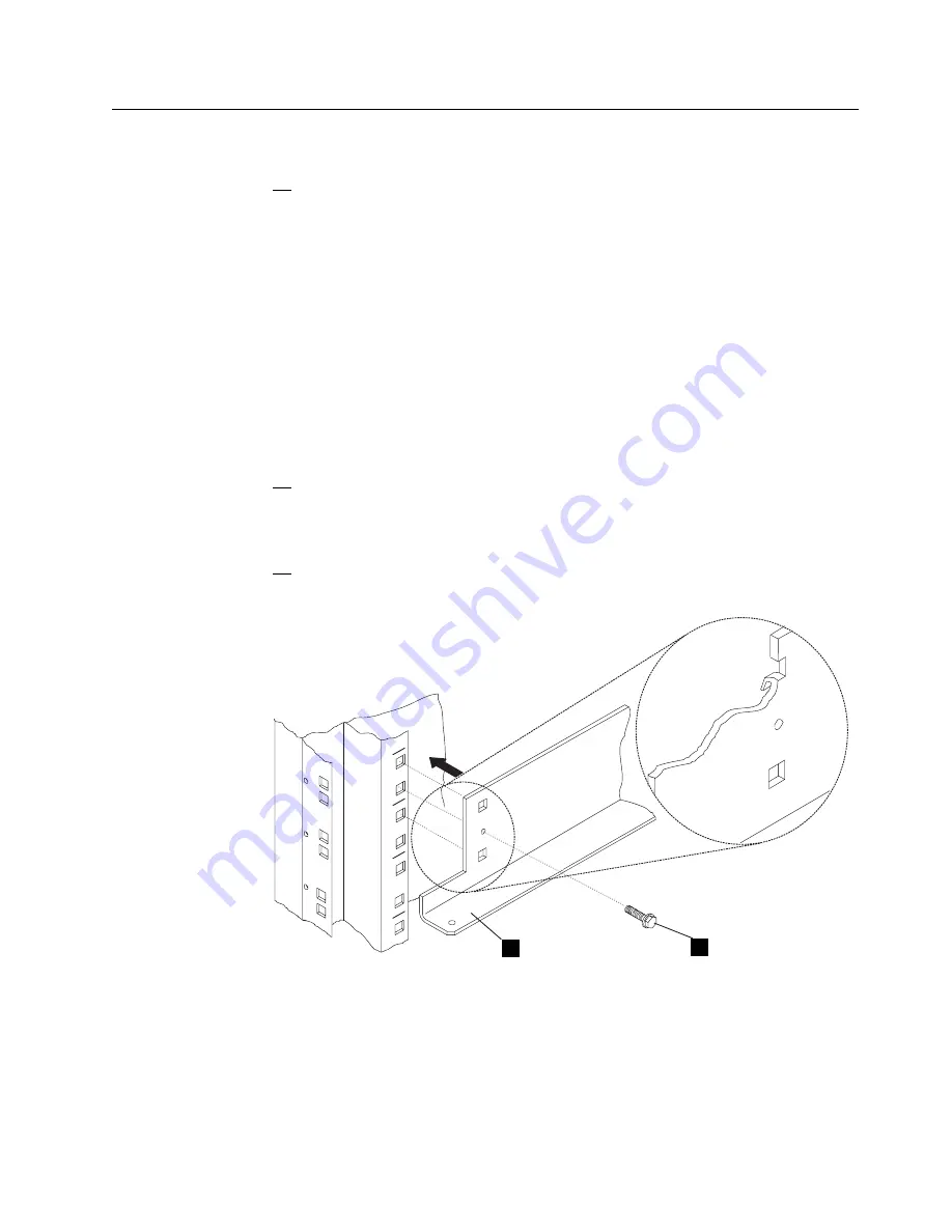
3. Install two brackets 

.1/

 (PN 58G5793) using four screws 

.2/

 (PN

2665527) in the controller expansion as shown in Figure 1-2.

XX

XX

XX

1

2

Figure  1-2. Brackets Installation


Chapter 1. Installing and Setting Up Your MAE

1-5

Содержание FlashSystem 900

Страница 1: ...3746 Nways Multiprotocol Controller Models 900 and 950 Multiaccess Enclosure Installation and Maintenance Starting from EC F12720 SY33 2124 02...

Страница 2: ......

Страница 3: ...3746 Nways Multiprotocol Controller Models 900 and 950 Multiaccess Enclosure Installation and Maintenance Starting from EC F12720 SY33 2124 02...

Страница 4: ...form for readers comments appears at the back of this publication If the form has been removed address your comments to Department CGFA Design Information Development IBM Corporation PO Box 12195 Rese...

Страница 5: ...ed xxiii Where to Find More Information xxiv World Wide Web xxiv Online Documentation from CD ROM xxv Service Personnel Definitions xxv Chapter 1 Installing and Setting Up Your MAE 1 1 Overview 1 2 In...

Страница 6: ...ng Parallel Channel Adapters 3 23 Concepts 3 23 Rules for Parallel Channel Adapter Testing 3 23 Preparing the Wrap Blocks 3 24 Running the Parallel Channel Adapter External Wrap Tests 3 27 Installing...

Страница 7: ...upervisory Password 5 15 Updating System Firmware 5 16 Displaying the Event Error Log 5 23 Viewing or Setting Vital Product Data 5 24 Manipulating the Dead Man Timer 5 27 Setting Up Remote Initial Pro...

Страница 8: ...Publications Update 6 17 Parts Disposition 6 17 Machine Records 6 17 Chapter 7 Removing or Relocating Your Multiaccess Enclosure 7 1 Deleting the Configuration Parameters 7 2 Disconnecting the MAE fro...

Страница 9: ...ing WAN Reroute after You Have Disabled it F 5 Spare Interfaces F 5 Appendix G Hardware Error Codes G 1 Appendix H Parts Listing H 1 Assembly 1 Final Assembly Multiaccess Enclosure H 2 Appendix I Mult...

Страница 10: ...I 22 Cable List I 22 V 35 Serial Cable I 23 Interchange Circuits I 23 Cable List I 23 V 35 Direct Attachement Cable I 24 Interchange Circuits I 24 Cable List I 24 V 36 Serial Cable I 25 Interchange Ci...

Страница 11: ...I 44 Bus and Tag Upstream Cable I 46 Bus and Tag Downstream Cable I 48 Other Cables I 50 Appendix J Bibliography J 1 Customer Documentation for the 3746 Model 950 J 1 Service Documentation for the IBM...

Страница 12: ...x 3746 9X0 MAE Installation and Maintenance...

Страница 13: ...0 SIE Cassette 1 19 1 22 MAE 1 22 1 23 MAE 1 23 1 24 Install Multiaccess Enclosure 1 23 1 25 Install Multiaccess Enclosure 1 24 1 26 Service LAN Addresses 1 24 1 27 SP Customization Message 1 25 1 28...

Страница 14: ...mization Message 4 21 4 13 SP Customization Completed 4 21 4 14 Service Processor Customization 4 28 4 15 Service LAN addresses 4 28 4 16 Removal of the Multiaccess Enclosure 4 52 5 1 System Managemen...

Страница 15: ...Service Processor based on 6275 I 1 I 2 Cables for Connection Between the Multiaccess Enclosure 3746 Models 900 950 and to Service Processor based on 7585 I 2 I 3 Cable Part Number 43G3953 I 3 I 4 Ca...

Страница 16: ...RJ 48 T1 ISDN Pri Cable I 31 I 44 RJ 48 T1 ISDN Pri Cable Pin Assignment I 31 I 45 E1 ISDN Pri Cable I 32 I 46 E1 ISDN Pri Cable Pin Assignment I 32 I 47 RJ 45 J1 ISDN Pri Cable I 33 I 48 RJ 45 J1 ISD...

Страница 17: ...M Intellectual Property Department in your country or send inquiries in writing to IBM World Trade Asia Corporation Licensing 2 31 Roppongi 3 chome Minato ku Tokyo 106 Japan The following paragraph do...

Страница 18: ...must accept any interference received including interference that may cause undesired operation Industry Canada Class A Emission Compliance Statement This Class A digital apparatus complies with Canad...

Страница 19: ...n solch einem Fall ist der Abstand bzw die Abschirmung zu der industriellen St rquelle zu vergr ern Anmerkung Um die Einhaltung des EMVG sicherzustellen sind die Ger te wie in den IBM Handb chern ange...

Страница 20: ...ve voltages An excessive voltage is one which exceeds 42 4 V peak ac or 60 V dc They interface with the 3746 Model 900 or 3746 Model 950 using Safe Extra Low Voltages only In order to maintain the ind...

Страница 21: ...h Java and all Java based trademarks and logos are trademarks or registered trademarks of Sun Microsystems Inc in the United States and or other countries Microsoft Windows Windows NT and the Windows...

Страница 22: ...xx 3746 9X0 MAE Installation and Maintenance...

Страница 23: ...contain excessive voltages An excessive voltage is one that exceeds 42 4 V peak ac or 60 V dc They interface with the IBM 3746 Expansion Unit Model 900 and IBM 3746 Nways Multiprotocol Controller Mod...

Страница 24: ...6 Input power voltage 7 Test of emergency power OFF control power switch 8 Power ON indicator xxii 3746 9X0 MAE Installation and Maintenance...

Страница 25: ...sure It also gives procedures to customize the multiaccess enclosure parameters Chapter 2 Presents the software maintenance procedures for the multiaccess enclosure Chapter 3 Gives the procedures for...

Страница 26: ...stallation and Integration GA27 4234 3745 Communication Controller Models A and 3746 Models 900 and 950 Serial Line Adapters GA27 4235 3745 Communication Controller Models A and 3746 Models 900 and 95...

Страница 27: ...disk drive of the SP 2 From the MOSS E primary menu click on Information 3 Double click on CD ROM documentation 4 Then if you want to display the CCP documentation click on Documentation 5 Click on La...

Страница 28: ...xxvi 3746 9X0 MAE Installation and Maintenance...

Страница 29: ...onnecting the MAE to a 6275 1 12 Step 3 3 Other MAE Cables Installation 1 13 Single ac Outlet Distribution Box 1 13 Dual ac Outlet Distribution Box 1 14 Step 4 Installing the SIE Cassette in the 3746...

Страница 30: ...ere are two links between the 3746 and the MAE 1 A serial link which is mandatory between the Switch Interface Extender SIE card in the 3746 and the Switch Adapter Card SAC card in the MAE 2 A Token R...

Страница 31: ...he MAE Step 2 Installing the MAE on page 1 5 3 Connect the MAE to the Service Processor Step 3 1 Connecting the MAE to a 7585 on page 1 11 Step 3 2 Connecting the MAE to a 6275 on page 1 12 4 Install...

Страница 32: ...amaged Store these disks in a safe place service drawer is fine 4 Before starting the installation connect to the following web site http www lagaude ibm com 3746pe and download all mandatory fixes ac...

Страница 33: ...installation kit One ac outlet distribution box if ordered when the MAE has two power supplies 2 According to the units to be installed in the controller expansion determine the location where you are...

Страница 34: ...d Power Supply Removal 5 Refer to Figure 1 4 remove the four screws 1 installed on the MAE frame then install on the left and right side of the MAE two brackets 2 PN 0782961 using four screws 3 PN 162...

Страница 35: ...ptive nuts from the brackets position 1 3 2 Z Z View Z Figure 1 5 Captive Nuts Installation 7 At the back of the controller expansion with the help of a second CE set the MAE on the brackets and faste...

Страница 36: ...Appendix B MAE Adapters Plugging Rules on page B 1 Figure 1 7 Installing Fan Tray and Power Supply Do you have to install a second ac outlet distribution box Yes go to Step 9 No go to Step 17 on page...

Страница 37: ...63F2459 to the new ac outlet distribution box 12 Install the ac outlet distribution box B close to the first ac outlet distribution box and fasten using two screws C PN 1621230 A C B Screw Lockwasher...

Страница 38: ...or ask the customer to switch ON the circuit breaker to be used for the ac outlet distribution box 16 Verify that the phase is distributed as shown below if not notify the customer and do not proceed...

Страница 39: ...cation of the service processor access unit 8228 service ring SPAU 2 Connect cable 4 PN 782960 on top of the PCMCIA card then plug the PCMCIA card into the system card into any of the two slots and th...

Страница 40: ...pter 2 PN 73G8314 into any free location of the service processor access unit 8228 service ring SPAU 2 Connect cable 4 PN 782960 on top of the PCMCIA card then plug the PCMCIA card into the system car...

Страница 41: ...Multiaccess Enclosure 2nd Power Supply Optical Disk Drive CD ROM Drive or RSF Modem 7858 Display Network Node Processor A Service Processor AC Input Figure 1 15 Power Plugging on a Single ac outlet D...

Страница 42: ...tions for example Ethernet Bridge AC Input AC Input Optical Disk Drive CD ROM Drive or RSF Modem 7858 Display Network Node Processor A Network Node Processor B Service Processor Multiaccess Enclosure...

Страница 43: ...cassette Note The SIE can be installed into any slot 07G A1 H to P in the basic enclosure or 07E 07D A1 D to P in the first or second expansion enclosure But when a CLP controls 3 or 4 LICs the adjac...

Страница 44: ...stripe should be aligned with the edge of the receptacle to ensure that the aid is firmly seated Yellow Indicator Lamp 1 2 3 4 Figure 1 18 Use of the 8228 Setup Aid The light will glow brightly when t...

Страница 45: ...er or supervisor Note The 8228 Setup Aid is to be used only in setting up the 8228 either initially or after relocating the 8228 It should never be used when the network is operating 6 Install the 822...

Страница 46: ...installed in location 1 of the MAE to any free plugs 1 to 8 of the 8228 2 Obtain from your customer the cable s 3 PN 72F1236 9M 30 Ft or any longer token ring cables Plug these cables from the 8228 a...

Страница 47: ...from the MAE to the 3746 board where the SIE cassette is installed 3 In the 3746 9X0 connect cable 5 to the SIE cassette 1 connector 2 Note This card can be plugged in any position of the basic or exp...

Страница 48: ...Go to Step 6 Customizing the MAE on page 1 21 1 20 3746 9X0 MAE Installation and Maintenance...

Страница 49: ...MCIA TR card 1 Power ON the MAE 2 Double click on the 3746 9X0 icon 3 Click on Multiaccess Enclosure Management 4 Now double click on ASCII Console 5 Press the Reset button on the MAE 6 Several window...

Страница 50: ...s window select option 4 Utilities 10 ____ Using the arrows keys select 11 Remote Initial Program Load Setup and press Enter 1 IP Parameters is selected press Enter again Figure 1 22 MAE 1 22 3746 9X0...

Страница 51: ...dress Subnet Mask then press Enter Note These IP addresses must be set according to the values given to the service ring IP parameters refer to For the multiaccess enclosure on page C 1 Figure 1 23 MA...

Страница 52: ...re 1 25 Install Multiaccess Enclosure 15 Enter the MAE IP address same value recorded in step 11 on page 1 23 as Client IP address then click on OK Figure 1 26 Service LAN Addresses 1 24 3746 9X0 MAE...

Страница 53: ...leted click on Close Note Verify that the MAE link icon is green 19 Now double click on ASCII Console 20 Press the Reset button on the MAE 21 Several windows are displayed during tests Wait until the...

Страница 54: ...Firmware Update panel is displayed Figure 1 30 MAE Attention Do not power off the multiaccess enclosure during the process of updating the firmware If the update fails the multiaccess enclosure will...

Страница 55: ...om the F W Update Options menu select 3 Use a Local Image File then press Enter 27 Follows the prompts enter the Local File Name c firm ld then press Enter Chapter 1 Installing and Setting Up Your MAE...

Страница 56: ...the System Firmware Update window it is mentionned that you have the same level of system firmware press Enter then Escape the go to Step 34 on page 1 29 Otherwise continue with the following Step 30...

Страница 57: ...the recovery image 32 A completed message appears when the firmware is updated 33 Press Enter to restart the system 34 Perform a general IML on the MOSS E View screen double click on the 3746 9x0 icon...

Страница 58: ...6 900 Installation Guide SY33 2114 if you are installing a 3746 900 The 3746 950 Installation Guide SY33 2107 if you are installing a 3746 950 Or if you are installing a MAE on a 3746 9X0 already inst...

Страница 59: ...r related to the multiaccess enclosure go to the START page of the 3746 950 Service Guide SY33 2108 3746 900 Or the 3746 900 Service Guide SY33 2116 3746 950 All the procedures to perform the problem...

Страница 60: ...re two versions of the code loaded on the SP and NNP hard drives the active version A and the non active version B When updating the LIC from the CD ROM on the SP hard drive we apply changes on the no...

Страница 61: ...ultiaccess Enclosure MAE Management In the code levels window you can find The MAE LIC installed on banks A B MAE disk The MAE LIC installed on SP active version SP disk Figure 2 3 Install Remove Chan...

Страница 62: ...nt double click on Switch to non active version Figure 2 4 SP Change Management 5 ____ The level of the active and non active version of the MAE LIC is now displayed Figure 2 5 Active Non active Versi...

Страница 63: ...e code currently installed and the level of the code to be installed Use the installation instructions shipped with the LIC to upgrade the LIC and the firmware of the MAE A copy of the installation in...

Страница 64: ...BM3745 4 ____ Double click on the Service Processor icon 5 ____ Click on Change Management 6 ____ Double click on Manage Microcode Fixes 7 ____ Click on View click on Change directory path 8 ____ Ente...

Страница 65: ...7 Manage Microcode Fixes 13 ____ Click on the lines of the MCFs to be applied see example in the Figure 2 8 14 ____ Click on Options and from the Options pull down menu click on Activate microcode fi...

Страница 66: ...icrocode Fixes e ____ Click on View click on Change directory path f ____ Enter the directory path J MCF g ____ Click on OK and verify the MCFs status it must be ACT 17 ____ Click on the System Menu i...

Страница 67: ...ard drive to the MAE hard drive Figure 2 10 Install Remove Change LIC on MAE 21 ____ When completed click on Close to exit from the function 22 ____ From the MAE management screen double click on Sele...

Страница 68: ...____ Verify the MCFs status a ____ Enter the Service Processor maintenance password b ____ Double click on the Service Processor icon c ____ Click on Change Management d ____ Double click on Manage Mi...

Страница 69: ...e Change LIC on MAE 13 ____ When completed click on Close to exit from the function 14 ____ From the MAE management screen double click on Selective IML on MAE to reboot the MAE Chapter 2 Maintaining...

Страница 70: ...n into the MAE Figure 2 13 MAE MOS Console 3 ____ Enter Talk 6 or t 6 list device then press Enter Note In this configuration example one token ring adapter is plugged in slot 1 the two ports are used...

Страница 71: ...ime LEDs which indicate the presence of AC DC voltages or presence of overcurrent condition System Card LEDs After power on reset POR the green and yellow LEDs will remain on until successful completi...

Страница 72: ...ight emitting diodes LEDs that indicate how the unit is functioning SAC Card SAC Card LEDs Green and Yellow System Card Power Supply Adapter Card Figure 3 1 Power Supply System Card SAC Card and Adapt...

Страница 73: ...g normally Blinking Loading from hard file OK Yellow On MAE is not configured Quick config is running on MAE Card hardware has a fault Adapter Card Status LEDs Meaning OK Green On Adapter is operating...

Страница 74: ...Name Telephone Number System Administrator Service Representative 1 The port LEDs of the multiport WAN adapters FC 3282 FC 3291 and FC 3292 reflect the status of one or more of the ports 3 4 3746 9X0...

Страница 75: ...has been configured Note If you can not load the operational code refer to Preparing the Multiaccess Enclosure Hard Disk on page 3 18 Diagnosing Operational Code and Configuration Problems Generally e...

Страница 76: ...minutes check the status of the LEDs on the front of the multiaccess enclosure The LEDs on the multiaccess enclosure should have the following status Y Y Y Y Y Y Y Y Y Y Y A B 1 5 2 6 3 7 4 8 Table 3...

Страница 77: ...C CARD is OK When the LED is ON that indicates that MAE is not configured Quick config is running on MAE SAC hardware has a fault PCMCIA Port 1 yellow on system card OFF Device has passed test PCMCIA...

Страница 78: ...ce the system card See Chapter 4 Multiaccess Enclosure FRU Exchange on page 4 1 LED Status Action ac indicator LED on a power supply is OFF Step 034 on page 3 12 dc indicator LED on a power supply is...

Страница 79: ...e the power supply See Chapter 4 Multiaccess Enclosure FRU Exchange on page 4 1 Restart the verification procedure Go to Step 001 on page 3 6 011 Replace the adapter See Chapter 4 Multiaccess Enclosur...

Страница 80: ...ccordingly After relocating the adapters are all wrong slot LEDs OFF Yes No 019 Call your support center for assistance 020 Restart the verification procedure Go to Step 001 on page 3 6 021 A yellow L...

Страница 81: ...no device plugged into slot If a PCMCIA device is plugged into a slot and LED is ON reseat the PCMCIA device and press reset on system card If the LED is still ON replace the PCMCIA device 028 The har...

Страница 82: ...Restart the verification procedure Go to Step 001 on page 3 6 033 Wait for the end of configuration then restart the problem determination 034 You are at this Step because the ac indicator on a power...

Страница 83: ...he fuse OK Yes No 043 Switch to OFF all the units controlled by this fuse Exchange the defective fuse Switch ON all the units controlled by this fuse Step 043 continues F2 F1 Fuse Location on ac outle...

Страница 84: ...Once you have identified the faulty unit continue with Step 053 on page 3 15 046 Suspect the ac wall socket 047 Check the corresponding fuse Is the fuse OK Yes No 048 Switch to OFF the defective unit...

Страница 85: ...ter 4 Multiaccess Enclosure FRU Exchange on page 4 1 After power exchange check the ac LED Is the ac Power LED now ON Yes No 054 Call your Support Center for assistance 055 Restart the verification pr...

Страница 86: ...terminators have been interchanged when you are using a cabling scheme that uses the Channel Interface out 4 Total bus or tag cable length is greater than the maximum length of 113 m 370 feet To calcu...

Страница 87: ...e Perform the action indicated by the diagnostic test 003 Did you replace a Parallel Channel Adapter Yes No 004 Connect all communication cables to their respective networks Return the multiaccess enc...

Страница 88: ...move MAE c Click on Yes to confirm d When completed click on Close 2 Power ON and verify the LEDs See Adapter Card Status on page 3 3 3 Several windows are displayed during tests Wait until the Boot I...

Страница 89: ...ter Attention This formats the hard disk and destroys all data on the hard disk h Follow the prompts to start HDD formatting i At the end of formatting the message Format Complete Successful is briefl...

Страница 90: ...100 Mbps Ethernet UTP 85H7913 LIC 289 85H9703 FC 3289 1 Port HSSI 86H0974 for adapter 86H0973 for cable LIC 290 85H4874 FC 3290 6 Port V 35 V 36 CRD 72F0168 V 35 BRICK 72F0167 V 36 CBL 73H2508 LIC 291...

Страница 91: ...96 OCTOPUS CABLE 6 LIC 282 WRAP PLUG 33F8985 8 PORT RS232 WRAP PLUG 68F7208 LIC 291 06H3358 WRAP PLUG 52G3378 8 PORT X 21 CABLE WRAP PLUG 06H3357 Figure 3 2 LIC 282 and LIC 291 Wrap Support Chapter 3...

Страница 92: ...WRAP PLUG 73H2508 6 PORT V 35 V 36 WRAP PLUG 72F0168 V 35 V 36 BRICK LIC 290 05F2044 WRAP PLUG 72F0167 6 PORT V 35 V 35 CABLE V 35 V 36 WRAP PLUG 72F0168 V 35 V 36 Figure 3 3 LIC 290 Wrap Support 3 2...

Страница 93: ...ional 1 First trace the V cables and the Channel Interface Cables from the Parallel Channel Adapters that you are testing to their input and output connectors 2 Even if you are not testing additional...

Страница 94: ...s enclosure at the end of a channel follow these steps using the following figure Before After Note W T T T W T T W Wrap Block Terminator MAE MAE To Host To Host Figure 3 4 Single Parallel Channel Ada...

Страница 95: ...er use the figure to determine how you want to connect your cables and go to Step 1 on page 3 26 Before After Note W T Wrap Block Terminator T MAE MAE MAE To Host T MAE MAE MAE To Host T W Parallel Ch...

Страница 96: ...Parallel Channel Adapter Continue with Step 2 No Plug the single V cable end of the Parallel Channel Adapter that is not being tested into the Parallel Channel Adapter that is connected to the host C...

Страница 97: ...This tests the Parallel Channel Adapter the V cable and the Channel Interface Cables Run external wrap tests of the adapter and the cables in the following sequence 1 The adapter see Figure 3 6 2 V ca...

Страница 98: ...Male Female Female Terminator PN 25L 4747 Wrap PN 7IF1184 V Cable Figure 3 7 V cable Wrap Test Connections 3 28 3746 9X0 MAE Installation and Maintenance...

Страница 99: ...Cable Gray Terminator PN 25L 4747 BUS in TAG in TAG Wrap PN 8575338 BUS Wrap PN 8575337 V Cable Black Gray Figure 3 8 Channel Interface in Wrap Test Connections Chapter 3 Multiaccess Enclosure Proble...

Страница 100: ...e out Cable Gray Black BUS in BUS out TAG in TAG out TAG Wrap 8575338 TAG Terminator 2282676 BUS Wrap 8575337 BUS Terminator 2282675 V Cable Black Gray Figure 3 9 All Cables Wrap Test Connections 3 30...

Страница 101: ...able Black Gray BUS out TAG out TAG Terminator 2282676 BUS Terminator 2282675 Wrap PN 7IF1184 V Cable Black Figure 3 10 Channel Interface out Wrap Test Connections Chapter 3 Multiaccess Enclosure Prob...

Страница 102: ...host computer operator to vary online those units attached to channels that are not being tested 5 Run the diagnostic test see Testing the Adapters on page 5 49 6 Do you want to repeat the Parallel Ch...

Страница 103: ...elect Bypass Switch with settings of S and B that are used to select or bypass this adapter respectively Select BypassSwitch Figure 3 11 Select Bypass Switch on V Cable Attention During testing and in...

Страница 104: ...Cable Female Female Gray Terminator PN 25L 4747 BUS in TAG in Black Channel in From Host Gray V Cable Black Gray Figure 3 12 Cabling to IBM multiaccess enclosure at the End of Channel 3 34 3746 9X0 MA...

Страница 105: ...Female Female Gray Black BUS in BUS out TAG in TAG out Black Black Channel in Channel out From Host Gray Gray V Cable Black Gray Figure 3 13 Cabling to IBM multiaccess enclosure in the Middle of the C...

Страница 106: ...in Cable Female Female Gray Terminator PN 25L 4747 BUS in TAG in Black Channel in From Host Gray V Cable V Cable Black Male Black Gray Gray Figure 3 14 Interconnected V cables 3 36 3746 9X0 MAE Instal...

Страница 107: ...a possibility of interconnecting multiaccess enclosure base Parallel Channel Adapters to 3172 models The following rules would apply in this case 1 The multiaccess enclosure base Parallel Channel Adap...

Страница 108: ...and Figure 3 13 on page 3 35 However multiple adapters can be interconnected in a serial fashion by connecting cables as shown in the figures that follow MAE or Figure 3 15 Standard Channel Connectio...

Страница 109: ...Guidelines for using the ESD tools are included inside the kit 1 Verify that the new feature and feature code you are installing to make sure that the customer s adapters are supported The feature co...

Страница 110: ...panel for that slot Slide the filler panel up and remove it Store it where you can find it to reinstall if you ever remove this adapter Parallel Channel Adapters Installation and Removal Use the follo...

Страница 111: ...cables on a flat surface and draw the cables together by tightening the screw near the center of the channel cable as shown 8 Connect the a Channel Interface in cable to the V cable b V cable to the...

Страница 112: ...ic tests see Testing the Adapters on page 5 49 to verify that the adapter and cables are OK 12 Tell the host computer operator that the channel can be returned to an operational state 13 Return to the...

Страница 113: ...Adapter by loosening the screws on the top and bottom of the connector 3 Pull the connector on the cable from the D shell connector on the adapter Parallel Channel Adapter Connector Toroid 4 Move the...

Страница 114: ...the pronged end The protective cover does not need to be removed for operation Protective Cover 1 Table 3 5 ESCON Cables Connect Disconnect To connect the adapter cables to the ESCON Adapter push the...

Страница 115: ...too tightly Overtightening the ties can damage the optical fiber cable Whenever possible fiber optic cables should be routed separately from wire based cables Cable Guide Bracket Cable Ties Frontof R...

Страница 116: ...terface Cable If you are replacing the Channel Interface Cable note the location of each cable or terminator block so that you can easily transfer it to the new Channel Interface Cable The channel end...

Страница 117: ...rom wire based cables Cable Guide Bracket Cable Ties V cable Adapter Cables 2 Remove the plastic cable strap from the cable guide arm 3 Route all cables and extender cables through the cable guide arm...

Страница 118: ...the multiaccess enclosure Store the manuals in or near the rack If you have added or removed any hardware the customer must reconfigure the application software You can now release the device to your...

Страница 119: ...e FRU Name Go to Power Supply If you have Only one power supply installed in your multiaccess enclosure go to Prerequisite Before some FRU Exchanging on page 4 2 Two power supply installed in your mul...

Страница 120: ...form Maintenance on MAE 5 The following window is displayed Click on Yes 6 The following window is displayed Click on OK 7 You should first received an alarm message saying MAE Concurrent Maintenance...

Страница 121: ...ower Supply on page 4 4 PCMCIA card Exchanging the PCMCIA Card on page 4 35 SAC Exchanging the SAC on page 4 24 Hard drive Exchanging the Hard Drive on the System Card on page 4 25 DIMM Exchanging the...

Страница 122: ...ews at the top and bottom and pulling the handle 4 Install the new power supply The power supply will slide into place on metal rails in the unit 5 Attach the power cord 6 Switch ON the power 7 Verify...

Страница 123: ...support up to 256 MB of total memory up to 64 MB DIMMs or two 128 MB DIMMs The third generation FRU system card FRU PN 31L4338 or PN 31L4336 supports up to 512 MB of total memory 4 Next the intent is...

Страница 124: ...and the Subnet mask Figure 4 2 Service LAN addresses e Then to exit from SP customization click on Previous Close and NO 2 Remove the MAE a Ask the customer to stop the traffic on all the Multiaccess...

Страница 125: ...ck on Yes f The following window is displayed Click on OK g You should first received an alarm message saying MAE Concurrent Maintenance in Progress h Click on OK i Return to the 3746 9x0 Menu j Doubl...

Страница 126: ...On the following window click on Yes to confirm n Wait until the message Operation successfully completed is displayed on the window o Click on Close 3 Remove the old system card 4 8 3746 9X0 MAE Inst...

Страница 127: ...handle the DIMM a Switch OFF each power supply b Label the cables on the system card Unplug the cables and the PCMCIA card c Loosen thumbscrews on the system card d Remove the system card and lay it...

Страница 128: ...e perpendicular to the face of the system card With the card in full contact with the rear of the Multiaccess Enclosure press the locking latches into the system card b Tighten the thumbscrews on the...

Страница 129: ...ard SAC Card LEDs Green and Yellow System Card Power Supply Adapter Card Figure 4 3 Power Supply System Card SAC card and Adapter Card LEDs 7 Update the Vital Product Data a From the 3746 9x0 Menu in...

Страница 130: ...er diags then press Enter Continue with Step 7d d On the System Management Services window select 4 Utilities then press Enter e On the System Management Utilities window select 9 View or Set Vital Pr...

Страница 131: ...Figure 4 5 MAE g Select slot B then press Enter Figure 4 6 MAE Chapter 4 Multiaccess Enclosure FRU Exchange 4 13...

Страница 132: ...igure 4 7 MAE i Press ESC twice then continue with Step 8 8 Set the IP addresses a Using the arrow keys select 11 Remote Initial Program Load Setup and press Enter 1 IP Parameters is selected press En...

Страница 133: ...enter the Client IP address MAE address of the PCMCIA card Server IP address service processor address Gateway IP address if no router on the ring enter the service processor IP address subnet mask th...

Страница 134: ...c Select Ping then press Enter d When PCMCIA Token Ring is prompted press Enter 4 16 3746 9X0 MAE Installation and Maintenance...

Страница 135: ...uccessful If not Go to Step 8b on page 4 15 and check or modify the addresses Check the speed 16 Mbps using the Adapter Parameters option in the Network Parameters window Check the cables Otherwise co...

Страница 136: ...the prompts enter the Local File Name c firm ld then press Enter d When the System Firmware Update window is displayed press Y e In the System Firmware Update window press Enter f When the message Fi...

Страница 137: ...he firmware from the recovery image i A completed message appears when the firmware is updated j Press Enter k Follow the prompts do not press F1 key and press the space bar when required to obtain th...

Страница 138: ...ll the MAE a Return to the 3746 9x0 Menu select Multiaccess Enclosure MAE Management b Double click on Install Remove Change LIC on MAE c Wait until the following window is displayed then click on Ins...

Страница 139: ...f When completed click on OK Figure 4 13 SP Customization Completed g The MAE code is now being installed it takes about 10 mn when completed click on Close Note Verify that the MAE link icon is gree...

Страница 140: ...er Configuration and Management option d The CCM window is displayed e Click on File in the title bar then select Open The Configuration List window is displayed f Select the name of the configuration...

Страница 141: ...h The MAE is rebooting i Wait for the MAE IML complete Be sure that the 3746 icon comes green 13 Notify the network administrator that you are finished repairing the Multiaccess Enclosure 14 Go to CE...

Страница 142: ...de it in until it is flush with the box Hold the locking latches so that they are perpendicular to the face of the system card With the card in full contact with the rear of the Multiaccess Enclosure...

Страница 143: ...the cables and the PCMCIA card 3 Loosen thumbscrews on the system card 4 Remove the system card and lay it on a soft non conductive surface Attention In the following Step be sure to support the hard...

Страница 144: ...it off the system card 8 Center the new hard drive inside the lines on the system card Note If you do not center the hard disk drive the electrical pins on the hard drive will be visible next to the h...

Страница 145: ...in full contact with the rear of the Multiaccess Enclosure press the locking latches into the system card 11 Tighten the thumbscrews on the face of the adapter card clockwise 12 Plug the PCMCIA token...

Страница 146: ...ice LAN addresses e Then to exit from SP customization click on Previous Close and NO 15 Return to the 3746 9x0 Menu click on Multiaccess Enclosure MAE Management The following window is displayed 16...

Страница 147: ...e click on Install Remove Change LIC on MAE b Click on Remove MAE c Click on Yes to confirm d When Operation successfully Completed is displayed click on Close 17 Double click on the ASCII Console opt...

Страница 148: ...and format the hard disk Follow the prompts If no errors occur press F1 when prompted then continue with Step 25 on page 4 31 If error code 30002000 occurs during format do the following a In the Sys...

Страница 149: ...ee Updating System Firmware on page 5 16 When it is done continue with the next Step 27 Restore the operational software on the new hard disk see Restoring the Image Code of the Multiaccess Enclosure...

Страница 150: ...les on the system card Unplug the cables and the PCMCIA card 3 Loosen thumbscrews on the system card 4 Remove the system card and lay it on a soft non conductive surface 5 Identify the faulty memory m...

Страница 151: ...ouch a grounded rack or other source of ground before you handle the DIMM 9 Remove the DIMM from the antistatic bag Inspect it for damage Always handle the DIMM by the ends preferably grasp it between...

Страница 152: ...ng from the Exchanging the System Card on page 4 5 return to Step 5 on page 4 9 Otherwise continue with the following Step 12 Go to Exchanging the System Card on page 4 5 4 34 3746 9X0 MAE Installatio...

Страница 153: ...e cable from the PCMCIA Card Y Y Y Y Y Y Y Y Y Y Y A B 1 5 2 6 3 7 4 8 Cable Unlocking Detail 2 Press the upper button to remove the PCMCIA card from the multiaccess enclosure Button Detail of PCMCIA...

Страница 154: ...2 Wait until you received an alarm message saying MAE IML Complete then click on OK The icon MAE Link should be green 13 Check and modify if necessary the PCMCIA speed setting using the following proc...

Страница 155: ...s Enter 8 Wait and when prompted press PF2 to save 9 Press Esc to quit the different windows to return to the Network Parameters window and continue with PCMCIA Checking PCMCIA Checking 1 In the Netwo...

Страница 156: ...3 Press Enter 4 You should obtain a window similar to the following 4 38 3746 9X0 MAE Installation and Maintenance...

Страница 157: ...following message is displayed Please press the space bar to obtain the console 8 Press the Space bar Console Granted to this interface is displayed 9 Close the MAE window 10 You are now on the 3746...

Страница 158: ...multiaccess enclosure that do not have a first generation system card PN 85H7916 or 30L5820 however you must install the new tray within 3 minutes of removing the defective tray to prevent overheating...

Страница 159: ...ee Adapter Card Status on page 3 3 5 Notify the network administrator that you are finished repairing the Multiaccess Enclosure 6 Go to CE Leaving Procedure on page 5 60 Chapter 4 Multiaccess Enclosur...

Страница 160: ...hich are LICs 282 290 and 291 you need to disable the WAN Reroute process before you remove the adapter See Disabling Interfaces that Have WAN Reroute Enabled on page F 4 d If you removing a Parallel...

Страница 161: ...zed adapter remove the daughter cards from the old adapter and put them onto the new adapter see Exchanging the ISDN Daughter Card on page 4 46 OK Wrong Slot 7 Install the new adapter Notice the notch...

Страница 162: ...ard is aligned with the plastic grooves and then slide it in until it is flush with the box Y Y Y Y OK Wrong Slot When the card makes full contact with the rear of the Multiaccess Enclosure press and...

Страница 163: ...bled on page F 4 you need to enable the WAN Reroute process See Enabling WAN Reroute after You Have Disabled it on page F 5 If you are replacing a Parallel Channel Adapter LIC 299 perform the Steps in...

Страница 164: ...nnect the daughter card from the adapter connector by gently pulling the daughter card up about an inch from the adapter d While raising both ends of the daughter card slide the daughter card to the s...

Страница 165: ...o the corners of the card d Install the two longer screws into the holes that are near the black cover on the card 4 Install the adapter Use the Steps beginning at step 7 on page 4 43 Chapter 4 Multia...

Страница 166: ...unseating or seating the adapter during removal or installation By doing so you prevent stripping the thumbscrews If you strip the thumbscrews you may not be able to seat or reseat the adapter proper...

Страница 167: ...rd is aligned with the plastic grooves and then slide it in until it is flush with the box Y Y Y Y OK Wrong Slot When the card makes full contact with the rear of the Multiaccess Enclosure press and s...

Страница 168: ...12 Power ON the Multiaccess Enclosure 13 Check that the green LED of the adapter comes ON and that the Wrong Slot LED is OFF If not check the adapter installation If the problem persists call the Netw...

Страница 169: ...too heavy fully populated 5 Remove the Power supplies Loosen the screws on each component and pull the handle System card see Exchanging the System Card on page 4 5 SAC see Exchanging the SAC on page...

Страница 170: ...Multiaccess Enclosure 7 Hold the Multiaccess Enclosure from the top of the front and bottom of the back and then slide it backward out of the rack 8 Place the Multiaccess Enclosure on a table 4 52 374...

Страница 171: ...top and bottom panels in place b While holding the side panel and the bracket 3 remove the top left and right screws 1 Side Panel 9 Remove the top panel To do this go to the rear of the Multiaccess En...

Страница 172: ...e backplane in place Top Rear 11 Remove the eight nuts and star washers located on the inside of the Multiaccess Enclosure Fan Tray Area Relative locations of the nuts viewed from the front of the box...

Страница 173: ...tic shield and press it up and toward you until all the bulkhead screws protrude through the chassis 17 Loosely insert the remaining screws on each side 18 Install and tighten the eight nuts and star...

Страница 174: ...lush with the box tighten the two screws 24 Install the SAC into slot A 25 Install the system card in slot B Make sure the card is aligned with the plastic grooves and then slide it in until it is flu...

Страница 175: ...nd MAP 0300 Multiaccess Enclosure Basic Verification on page 3 6 31 Notify the network administrator that you are finished repairing the Multiaccess Enclosure 32 Go to CE Leaving Procedure on page 5 6...

Страница 176: ...4 58 3746 9X0 MAE Installation and Maintenance...

Страница 177: ...osure depending the multiaccess enclosure status Select in the following table what you intend to do What you want to do Go to Run diagnostics on the complete multiaccess enclosure after installation...

Страница 178: ...Power off and power on the multiaccess enclosure Note Make sure the screen size for your terminal emulation software is set to 80 columns by 24 rows Connection in Attended mode is a TTY using limited...

Страница 179: ...he password and continue with Step 3 3 On the MOSS E View window double click on the 3746 icon 4 On the 3746 9x0 Menu click on the Multiaccess Enclosure MAE Management option The following window is d...

Страница 180: ...tions explain these services and provide instructions for using the associated panels Managing the Configuration on page 5 6 Selecting the Boot Sequence on page 5 7 Selecting a Device To Test on page...

Страница 181: ...tacked at the right of the panel Use the F1 Help key to get descriptions for the function keys associated with the firmware Obtaining Help Online helps are available for panels whenever the F1 key is...

Страница 182: ...y pressing F6 1 Select 1 Manage Configuration from the main menu as shown in Figure 5 1 on page 5 4 2 The System Configuration Information panel is displayed as shown in Figure 5 2 Note Only the field...

Страница 183: ...panel will be displayed Default boot devices are None IDE hard drive Network adapter IBM PCMCIA Modem Network adapter IBM SLIP Com 1 Direct 4 Highlight your choice and press Enter 5 Repeat step 3 and...

Страница 184: ...Figure 5 4 Current Boot Sequence 5 8 3746 9X0 MAE Installation and Maintenance...

Страница 185: ...e PowerPC CPU the System Board interrupts and the PCMCIA controller Test IDE devices This test runs on the IDE devices 1 Select 3 Select Device to Test from the main menu 2 The Select Device to Test p...

Страница 186: ...A menu listing the available utilities is displayed Figure 5 6 Figure 5 6 Utilities Selection Panel 3 Make your selection You will be prompted for additional information and messages are displayed to...

Страница 187: ...Power On Password from the utilities panel The Set Power On Password panel is displayed Figure 5 7 2 Type your new password and press Enter You are prompted to enter your new password again Note The...

Страница 188: ...ange the password 1 Select 2 Set Supervisory Password from the utilities panel The Set Supervisory Password panel is displayed Figure 5 8 2 Type your new password and press Enter You are prompted to e...

Страница 189: ...art Mode from the utilities panel The Unattended Start Mode Changed panel is displayed Figure 5 9 2 Press Enter Figure 5 9 Unattended Start Mode Changed Enabled Panel Note After you have enabled Unatt...

Страница 190: ...e using this utility 1 Select 4 Disable Unattended Start Mode from the utilities panel The Unattended Start Mode Changed panel is displayed Figure 5 10 2 This panel informs you that the Unattended sta...

Страница 191: ...the multiaccess enclosure 1 Select 6 Remove Supervisory Password from the utilities panel 2 The Remove Supervisory Password panel is displayed Figure 5 11 Figure 5 11 Remove Supervisory Password Panel...

Страница 192: ...Firmware Update panel is displayed Figure 5 12 System Firmware Update Panel Attention Do not power off the multiaccess enclosure during the process of updating the firmware If the update fails the mu...

Страница 193: ...ss Start 5 The following window appears Do not Click on any Function key 6 Return to the System Management Utilities window select TFTP a Remote Image file then press Enter Chapter 5 Multiaccess Enclo...

Страница 194: ...7 The following window appears Enter the local file name c firm ld Press Enter 8 On the following window Enter the remote file name firm ld Press Enter 5 18 3746 9X0 MAE Installation and Maintenance...

Страница 195: ...n Ring selected Press Enter 10 Put the current window in background by clicking on the Service Processor Menu by example 11 On the Select Firmware Update File select FIRM LD Press Enter Chapter 5 Mult...

Страница 196: ...12 On the System Firmware Update window Press Y 13 The following window is displayed press Enter 5 20 3746 9X0 MAE Installation and Maintenance...

Страница 197: ...Do not switch the system off The process erases the old firmware and copies the new firmware into flash memory If the machine is powered off before the process is complete you will need to reload the...

Страница 198: ...16 A completed message appears when the firmware is updated 17 Press Enter to restart the system 18 Press F1 when prompted to terminate the boot 5 22 3746 9X0 MAE Installation and Maintenance...

Страница 199: ...Display Event Error Log from the utilities panel then press Enter 2 The Error Log panel is displayed Figure 5 13 See Appendix G Hardware Error Codes on page G 1 for and explanation of the data that a...

Страница 200: ...m this panel you can select the type of vital product data you want to view or set The system card serial number field is the only field under the Hardware Vital Product Data menu that is modifiable F...

Страница 201: ...epending on the configuration of your system not all of the keywords listed are necessarily present or have meaningful values AT Main logic card type DS Text description of card FN FRU number PN Manuf...

Страница 202: ...oot flash level and ID NA Burned in MAC Address in ASCII Format ZB Burned in MAC Address in Hex Canonical Format TM Machine type and model F Feature Number BS Box serial number RC Recycle count Z0 Ven...

Страница 203: ...ires in 10 seconds This tool would be useful in some troubleshooting procedures 1 Select 10 Manipulate Dead Man Timer from the utilities panel then press Enter 2 A Dead Man Timer Options panel is disp...

Страница 204: ...r the IP address of the multiaccess enclosure and the host input PCMCIA adapter parameters or Ping from the multiaccess enclosure to the host Figure 5 16 Setup Remote Initial Program Load Panel If you...

Страница 205: ...m the System Management Services menu To access the System Management Services menu you have to either interrupt the boot up sequence or bring up the multiaccess enclosure in Attended mode The Change...

Страница 206: ...go to Step 5 on page 5 31 Otherwise continue with Step 2 2 In the Multiaccess Enclosure MAE Management window double click on the Enable MAE hard disk restoration option 3 The following window is dis...

Страница 207: ...e Multiaccess Enclosure MAE Management window then double click on the ASCII Console option a The following window is displayed Select 4 Utilities Chapter 5 Multiaccess Enclosure Firmware and Operatio...

Страница 208: ...Management Utilities window select 12 Change Management c On Change Management Software Control window select 10 TFTP Software Figure 5 17 TFTP Software Selection 5 32 3746 9X0 MAE Installation and M...

Страница 209: ...d Select Load Image then press Enter e Select 1 Bank A then press Enter Chapter 5 Multiaccess Enclosure Firmware and Operational Code 5 33...

Страница 210: ...nter i The Interface window is displayed with PCMCIA selected Press Enter j Put the current window in background by clicking on the Service Processor Menu window by example k Wait until the window Fig...

Страница 211: ...6 On Change Management Software Control window select 9 Set Boot Information 7 Select Bank A then press Enter Chapter 5 Multiaccess Enclosure Firmware and Operational Code 5 35...

Страница 212: ...12 On the Change Management Software Control window select 4 Control Dumping of Router then press Enter 13 Select Enable then press Enter 14 On the Change Management Software Control window press Esc...

Страница 213: ...ayed 19 Click on OK 20 If you are in this procedure after changing the hard disk on the system card continue with Step 20a Otherwise go to Step 21 on page 5 39 a Click on Install MAE Figure 5 18 Insta...

Страница 214: ...c Click on Yes to record your parameters Figure 5 20 SP Customization Message d When completed click on OK Figure 5 21 SP Customization Completed e The MAE code is now being installed it takes about...

Страница 215: ...following window click on Change LIC on MAE 22 Click on OK on the information message 23 On the Install Remove Change LIC on MAE window the name of files transfered appears Chapter 5 Multiaccess Enclo...

Страница 216: ...24 Wait until the following window is displayed Click on Close 25 Return to the procedure where you come from 5 40 3746 9X0 MAE Installation and Maintenance...

Страница 217: ...resence of diagnostic aids such as wrap plugs The Restore from Loop Test to prompt you to remove diagnostic aids that have been installed prior to testing Many of the diagnostic pages have help inform...

Страница 218: ...ontinue with Step 3 3 On the MOSS E View window double click on the 3746 icon 4 On the 3746 9x0 Menu click on the Multiaccess Enclosure MAE Management option The following window is displayed 5 Double...

Страница 219: ...each adapter 2 The Diagnostic Test History Log contains a summary of recent diagnostic testing activity 3 The Diagnostic Error Log contains error information for recent diagnostic tests that have dete...

Страница 220: ...r D Down B Back R Refresh h Help Figure 5 23 Sample of Device List Panel Showing Interfaces The Device List is the starting point for running a test It also provides a check to determine if all of the...

Страница 221: ...Disabled The Device Status and Control Page displays status and a menu of actions for the selected device The status fields that are displayed are dependent on the characteristics of the device The me...

Страница 222: ...device Diagnostic Status INACTIVE Diagnostic for the device is not running TESTING A testing process for the device is active and the device is being tested LOOP AND LOG A testing process for the dev...

Страница 223: ...hen the device must be disabled before any diagnostic test can be started This performs the same function as the disable command available at the router s monitoring talk 5 console Run Default Test Th...

Страница 224: ...istory of recent diagnostic tests that have been executed View Hardware Error Log Displays a list of errors detected by diagnostic tests 3 Type E and press Enter to exit the diagnostic menus and retur...

Страница 225: ...er also has optical power page 5 57 and light reception tests page 5 53 Complete the following steps to test a faulty or newly installed Adapter Power on the multiaccess enclosure Run diagnostics on t...

Страница 226: ...t a device to test for example type 4 for ESCON to test the ESCON channel adapter in slot 4 4 Select Run Interactive Test The Test Options menu appears Screen 1 of 1 Test Options LIC 287 ESCON Channel...

Страница 227: ...t This is a long running test The Device Status and Control Menu is displayed again Note that the Diagnostic Status is TESTING This indicates that the tests are running and will take about 3 minutes t...

Страница 228: ...e fiber connection Select Back to see the results of the test Select B Back R Refresh H Help b 8 Remove the wrap plug 9 Reconnect the network cable to the adapter 10 Select b to view the results of th...

Страница 229: ...ncluding external wrap test Individual tests 3 PCI BUS 4 PROCESSOR 5 MEMORY 6 MEMORY PROT 7 TIMER 8 AIB 9 WRAP PLUG 10 OPTICAL POWER 11 LIGHT RECEPTION Select 1 11 or B Back R Refresh H Help 11 2 Ente...

Страница 230: ...are Error Log Select 1 2 or B Back R Refresh H Help r 4 Keep entering r until the Diagnostic Status changes from TESTING to MESSAGE At this point the following panel is displayed Screen 1 of 1 Restore...

Страница 231: ...c cable Screen 1 of 1 Test Results LIC 287 ESCON Channel Adapter Slot 4 Net 0 Operational Status Diagnostic Status Fault Status Network Connection NOT CONFIGURED INACTIVE NON ISOLATED UNKNOWN No light...

Страница 232: ...If you select option 3 4 6 or 7 the results will be displayed immediately If you select test option 1 2 5 8 9 or 11 all long running tests the result may not be available for a few minutes In this ca...

Страница 233: ...KNOWN Do not remove this device while testing Select one of the following test options 1 Run all tests excluding external wrap test 2 Run all tests including external wrap test Individual tests 3 PCI...

Страница 234: ...t the black biconic connector of the test cable to the biconic receptacle on top of the power meter 8 Enter 1 to start the test as indicated in the following example Screen 1 of 1 Setup For Optical Te...

Страница 235: ...u may now record the power level displayed on the optical power meter A properly functioning ESCON should have a power level of 21 0dBm or more for example 18 0dBm Select 1 Stop test when you have fin...

Страница 236: ...on 3745 or 3746 be sure to have restore them at a correct status for customer application MOSS online 3746 online FRU active in CDF E and MAE Link icon green see note 2 Ask the customer to restart hi...

Страница 237: ...Installing Options Chapter 6 Installing Options Installing a Dual Power Supply FC 3500 6 2 Installing an Adapter FC 32XX 6 6 After Installation 6 17 Copyright IBM Corp 1998 1999 6 1...

Страница 238: ...500 Preparation 1 Familiarize yourself with the purpose and details of these installation instructions 2 Check all the items and count the parts listed on the B M s to be installed to determine that a...

Страница 239: ...Installing Options Installation Time BM Installed Machine Hours System Hours Nb of CE 86H0248 0 0 0 0 1 Tools Materials Required None Chapter 6 Installing Options 6 3...

Страница 240: ...the filler plate 4 Unpack the power module and verify that the power switch is set to OFF 0 5 Insert the power module into the Multiaccess Enclosure 6 Position the screws then slide the module into it...

Страница 241: ...ndicator LED is OFF If the AC Indicator LED is OFF or the Overcurrent Indicator LED is ON refer to Chapter 3 Multiaccess Enclosure Problem Determination on page 3 1 12 Close the front and back doors o...

Страница 242: ...C 3298 or 86H0247 2 Port Token Ring Adapter FC 3280 or 86H0246 2 Port Ethernet Adapter FC 3281 or 86H0238 8 Port EIA 232E V24 Adapter FC 3282 or 86H0241 1 Port ISDN PRI T1 J1 Interface Adapter FC 3283...

Страница 243: ...Installing Options Programming None Chapter 6 Installing Options 6 7...

Страница 244: ...y capability of the 3746 9x0 Description Install an adapter in the 3746 Nways Multiaccess Enclosure Installation Time See BM to be installed BM Installed Machine Hours System Hours Nb of CE 0 5 0 0 1...

Страница 245: ...e A 1 and refering to Appendix B MAE Adapters Plugging Rules on page B 1 identify the location where the adapter has to be installed 3 Remove the filler plate 4 Insert the adapter module into the mach...

Страница 246: ...connection Configuring the Adapter 1 In the Main Menu click on Network Node Processor NNP Management option 2 In the Network Node Processor NNP Management window double click on the Controller Configu...

Страница 247: ...age may appear saying MAE configuration is updated 7 The following window is displayed 8 Double click on the MAE address range Wait for the Nothing Selected window is displayed 9 Press Ctrl Esc 10 The...

Страница 248: ...Installing Options Note By clicking on the on the left side of the icon the view is expanded 11 Expand the Devices The following window is displayed 6 12 3746 9X0 MAE Installation and Maintenance...

Страница 249: ...isplayed 13 Click on the Slots option The Slot Browser window similar to the following is displayed 14 Select the slot where you want to add or remove an adapter by clicking on the desired position A...

Страница 250: ...er option Otherwise click on the appropriate adapter The Slot Browser window is again displayed with the change 16 Press Ctrl Esc 17 The Window List is displayed Click on the Navigation Window The Nav...

Страница 251: ...talling Options 18 If you have several ports on the adapter click on Ports option Windows are displayed to help you 19 Press Ctrl Esc to return to the Navigation Window Chapter 6 Installing Options 6...

Страница 252: ...1 When the needed options have been modified press Ctrl Esc to return to the Navigation Window 22 In Navigation Window Click on Configure to exit MAE and return to 3746 resources Click on Yes to save...

Страница 253: ...ated in the rental machine directions below For EMEA APG AG Areas refer to Hardware and General Service Code Description For Domestic Areas return parts to the customer Rental Machines Provide all par...

Страница 254: ...Installing Options 6 18 3746 9X0 MAE Installation and Maintenance...

Страница 255: ...ter 7 Removing or Relocating Your Multiaccess Enclosure Deleting the Configuration Parameters 7 2 Disconnecting the MAE from Power and Removing Cables 7 3 Preparing the MAE for Shipment 7 3 Copyright...

Страница 256: ...___ Double click on the 3746 9x0 icon 2 ____ Click on Multiaccess Enclosure MAE Management double click on Install remove Change LIC on MAE Figure 7 1 3746 9X0 Multiaccess Enclosure Management 3 ____...

Страница 257: ...are from the controller expansion see Step 2 Installing the MAE on page 1 5 7 ____ If installed remove the second ac outlet distribution box Preparing the MAE for Shipment 1 ____ Pack the machine usin...

Страница 258: ...Installing Options 7 4 3746 9X0 MAE Installation and Maintenance...

Страница 259: ...wer Cord Power Cord To ac Outlet Distribution Box Switch Adapter Card Slot A System Card Slot B Token Ring Adapter 2 Port Basic to 3746 9x0 Token Ring Adapter PCMCIA to SPAU Adapters Slots X7 EIA 232...

Страница 260: ...SAC Card SAC Card LEDs Green and Yellow System Card Power Supply Adapter Card Figure A 2 Multiaccess Enclosure Components A 2 3746 9X0 MAE Installation and Maintenance...

Страница 261: ...installed then one additional adapter can also be installed A maximum of four ESCON adapters 3287 can be installed A maximum of four ISDN adapters 3283 or 3292 can be installed A maximum of two ATM ad...

Страница 262: ...also used for fast token ring FasTR One 4 port ISDN PRI Channelized T1 J1 interface adapter FC 3297 One 4 port ISDN PRI Channelized T1 Daughter card FC 3251 can be added to the base 4 port ISDN PRI Ch...

Страница 263: ...be used 3 If the 2 port Token Ring FC 3280 or 2 port Ethernet FC 3281 adapter is plugged into slot 7 and active then slot 8 cannot be used 4 If the 2 port Token Ring FC 3280 or 2 port Ethernet FC 328...

Страница 264: ...B 4 3746 9X0 MAE Installation and Maintenance...

Страница 265: ...Token Ring card plugged on the system card of the MAE 2 If no gateway specify the IP address of the service processor Table C 1 IP Addresses and Subnet Mask Client IP address multiaccess enclosure see...

Страница 266: ...C 2 3746 9X0 MAE Installation and Maintenance...

Страница 267: ...its installation processor type 7585 Example of units installation processor type 7585 MAE Example of units Installation SP and NNP Type 6275 Example of units Installation SP and NNP Type 6275 MAE Con...

Страница 268: ...NNP Type 7585 4U SP Type 9577 4U Modems 2U 7855 7857 7785 CD ROM Drive 2U Service Drawer 2U LCBB LCBE 4U SP Type 9685 12U MAE 13U Controller Expansion 37U Front View Optical Disk Drive 2U Reserved fo...

Страница 269: ...The values represent the size used to setup the units in the controller expansion it is not the size of the units themself 2 The attachment holes along each side of the controller expansion are divide...

Страница 270: ...10 10 9 9 8 8 7 7 6 6 24 24 25 25 26 26 27 27 28 28 Front View Rear View 8228 Drawer Drawer Display SP NNPA NNPB Figure D 3 Installing Captive Nuts and Brackets for the Display Drawer SP and NNP Type...

Страница 271: ...XX XX XX XX XX XX XX XX XX XX XX XX XX XX XX XX XX XX XX XX XX Front View Rear View 1st LCB 1st LCB 2nd LCB 2nd LCB 3rd LCB 3rd LCB 4th LCB 4th LCB Figure D 4 Installing Captive Nuts for LCBs Note Th...

Страница 272: ...XX XX XX XX XX XX XX XX XX XX XX XX XX XX XX XX XX XX XX XX XX XX XX XX XX XX XX XX XX XX XX XX XX XX XX XX XX XX XX XX XX XX XX XX XX XX Figure D 5 Installing Captive Nuts for 8229s Note This symbol...

Страница 273: ...XX XX XX XX XX XX XX XX XX XX XX XX XX XX XX XX XX XX XX XX XX XX XX XX XX XX XX XX XX XX XX XX XX XX XX XX XX Figure D 6 Installing Captive Nuts and Brackets for MAE Note This symbol identify the loc...

Страница 274: ...Node Processor A Network Node Processor B 1 2 3 4 5 6 7 8 9 10 11 12 13 14 15 16 17 18 19 20 21 22 23 24 25 26 27 28 29 30 31 32 33 34 35 36 LCB Figure D 7 Installing Brackets PN 58G5752 for Processor...

Страница 275: ...gure D 8 Units Installation in the Controller Expansion SP Type 7585 Service Processor Modem Network Node Processor A Network Node Processor B LCBB LCBE Multiaccess Enclosure Display Figure D 9 Units...

Страница 276: ...D 10 Units Installation in the Controller Expansion SP and NNP Type 6275 Service Processor Modem Network Node Processor A Network Node Processor B LCBB LCBE Multiaccess Enclosure Display Figure D 11 U...

Страница 277: ...F1 F1 J8 J8 J7 J7 J6 J6 J5 J5 J4 J4 J3 J3 J2 J2 J1 J1 Other Options for example Ethernet Bridge Other Options for example Ethernet Bridge Other Options for example Ethernet Bridge AC Input AC Input Op...

Страница 278: ...D 12 3746 9X0 MAE Installation and Maintenance...

Страница 279: ...configuration within a few hours How Software Files Are Managed To help you manage operational software upgrades and configurations the multiaccess enclosure has a software change management feature...

Страница 280: ...is reset will cause the currently ACTIVE file to become PENDING LOCAL is a status that makes a file ACTIVE only for one reset of the multiaccess enclosure Only one bank at a time contains an ACTIVE im...

Страница 281: ...me to retrieve all load modules belonging to this load image Notes a Information boxes appear as each load module is being transferred using TFTP Some time will transpire as each transferred load modu...

Страница 282: ...ror The multiaccess enclosure will dump memory onto the hard disk Once a successful dump has been taken the multiaccess enclosure attempts to restart Depending upon the failure of the multiaccess encl...

Страница 283: ...nfiguration file in BANK A CONFIG 1 remains unchanged and AVAIL The configuration that was in BANK B CONFIG 1 is overwritten by a copy of the configuration file that is in BANK A CONFIG 1 This copy re...

Страница 284: ...2 In the Network Node Processor NNP Management window double click on the Controller Configuration and Management CCM option 3 The following window is displayed 4 Click on File in the title bar then...

Страница 285: ...Open Selected Configuration 6 A message may appear saying MAE configuration is updated 7 The following window is displayed 8 Two cases must be considered a If the MAE is already installed and shown in...

Страница 286: ...th Step 11 on page E 9 b If the MAE is not yet shown in the window double click on the address range where you intend to install and configure the MAE Continue with Step 9 9 The following window is di...

Страница 287: ...ss Ctrl Esc 12 The Window List is displayed Double click on the Navigation Window The Navigation Window is displayed Note By clicking on the on the left side of the icon the view is expanded 13 Expand...

Страница 288: ...14 Expand the Adapters The following window is displayed E 10 3746 9X0 MAE Installation and Maintenance...

Страница 289: ...add or remove an adapter by clicking on the desired position A new window appears with a choice 17 If you are removing an adapter click on the No Adapter option Otherwise click on the appropriate adap...

Страница 290: ...List is displayed Click on the Navigation Window The Navigation Window is displayed 20 If you have several ports on the adapter click on Ports option Windows are displayed to help you E 12 3746 9X0 M...

Страница 291: ...0 and 950 Multiaccess Enclosure Planning GA27 4240 manual 23 When the needed options have been modified 24 Press Ctrl Esc to return to the Navigation Window 25 In Navigation Window Click on Configure...

Страница 292: ...ork The 3746 9x0 menu window is displayed Click on the Network Node Processor NNP Management option Double click on the CCM Controller Configuration and Management option The CCM window is displayed C...

Страница 293: ...then click on Activate Follow the prompts and wait until the following window is displayed Click on OK The MAE is rebooting Wait for the MAE IML complete Be sure that the 3746 icon comes green Append...

Страница 294: ...E 16 3746 9X0 MAE Installation and Maintenance...

Страница 295: ...the multiaccess enclosure and stopping the boot process with the F1 key It displays a menu with a number of options See Accessing the Firmware from the Service Processor on page 5 3 for more informat...

Страница 296: ...e Operational Diagnostics from the Service Processor on page 5 42 2 Type talk 5 and press Enter twice to reach the prompt 3 Type protocol and press Enter 4 Type ip and press Enter The prompt changes t...

Страница 297: ...ter port to remove or test an adapter Answer 1 Access the command line interface prompt see Accessing the Operational Diagnostics from the Service Processor on page 5 42 2 Type talk 5 and press Enter...

Страница 298: ...6prod html for the multiaccess enclosure or http www networking ibm com 376 376prod html for the 3746 Disabling Interfaces that Have WAN Reroute Enabled Question How do I ensure that WAN Reroute does...

Страница 299: ...though it may not be needed to back up a primary interface If this happens you can issue the talk 5 disable interface command to put the alternate interface back into the standby disabled state The fo...

Страница 300: ...F 6 3746 9X0 MAE Installation and Maintenance...

Страница 301: ...uption during last boot sequence update 00017007 PPC Board Security Maximum unsuccessful attempts to enter password was reached Time and date are logged 00020000 Memory Memory Memory test error run fu...

Страница 302: ...G 2 3746 9X0 MAE Installation and Maintenance...

Страница 303: ...Units column indicates that the part is non procurable and that the individual parts or the next higher assembly should be ordered NR Not Recommended in the Units column indicates that the part is pro...

Страница 304: ...Assembly 1 Final Assembly Multiaccess Enclosure 9 21 20 10 1 2 7 8 3 4 5 6 H 2 3746 9X0 MAE Installation and Maintenance...

Страница 305: ...rt ESCON Channel FC 3287 86H1005 1 LIC 288 Not Illustrated 1 Port 100Mbps Ethernet FC 3288 85H9703 1 LIC 289 Not Illustrated 1 Port HSSI FC 3289 85H4874 1 LIC 290 Not Illustrated 6 Port V 35 V 36 FC 3...

Страница 306: ...H 4 3746 9X0 MAE Installation and Maintenance...

Страница 307: ...work Node Processor A B To TIC3 3746 9X0 To TIC3 3746 9X0 To SIE Card 3746 9X0 To TIC3 of CBSP 3746 9X0 1 2 4 3 8 5 7 7 Multiaccess Enclosure PS2 PS1 Service Processor Service Ring SPAU 8228 8228 8228...

Страница 308: ...TIC3 3746 9X0 To TIC3 3746 9X0 To SIE Card 3746 9X0 To TIC3 of CBSP 3746 9X0 1 9 2 4 3 8 5 7 7 Multiaccess Enclosure PS2 PS1 Service Processor Service Ring SPAU 8228 8228 8228 10 S A C Figure I 2 Cabl...

Страница 309: ...ata Connector Pin 1 Pin 4 Figure I 3 Cable Part Number 43G3953 Pin Assignment 3 4 5 6 RJ45 Connector Data Connector 1 4 3 2 Shield Figure I 4 Cable Pin Assignment Part Number 43G3953 Table I 1 Cable f...

Страница 310: ...Cable between the Multiaccess Enclosure PCMCIA Card and the Service Processor Interchange Circuits for the Cable between the Multiaccess Enclosure and the Service Processor 4 5 12 13 3 6 9 14 17 RJ45...

Страница 311: ...ting Cable with RJ45 Connector to 8228 Part Number 73G8314 Balun Pin Assignment Data I O Connector Black Green Orange Red TP 3 7 TP 1 5 RJ 45 Connector 4T TP 12 8 18T TP 14 10 C1 C2 PIN 6 4 PIN 3 5 18...

Страница 312: ...tor Female P1 P2 1 1 5 5 Figure I 9 Cable Pin Part Number 782958 Interchange Circuits for the Cable between the Multiaccess Enclosure and the Service Processor 5 2 3 4 1 6 8 5 3 2 1 4 6 8 9 Pin Connec...

Страница 313: ...Multiaccess Enclosure Cables Adapter Cable Male Connector Female Connector P1 P2 Figure I 11 Adapter cable Part Number 782982 Appendix I Multiaccess Enclosure Cables I 7...

Страница 314: ...ble 6 part number 60G1066 to connect the standard LAN cable Female Connector P1 P2 1 5 6 9 1 2 3 4 5 6 7 8 Figure I 12 Adapter Cable Part Number 60G1066 Pin Assignment Table I 4 Adapter Cable Pin Assi...

Страница 315: ...troller Expansion Refer to Figure I 2 on page I 2 reference 8 for details IEC 320 C 14 IEC 320 C 13 15 Figure I 13 Power Cable for Units Connected to the ac Outlet Distribution Box Table I 6 Power Cab...

Страница 316: ...Wire Nbr Wire Color Connector 1 Position Connector 2 Position 1 2 3 4 5 SHIELD ORN BLACK RED GREEN GND 9 5 1 6 SHIELD ORN BLACK RED GREEN Table I 8 Cable Length Ordering Information for EMEA Part Numb...

Страница 317: ...m length 44 144 max Custom length 44 144 max Plenum Custom length Cable Between the 3746 SIE Cassette and the MAE SAC Card Refer to Figure I 2 on page I 2 reference 10 Male Connector Male Connector P1...

Страница 318: ...8 29 45 13 46 14 30 31 47 15 48 16 32 33 49 17 50 1 34 2 18 19 35 3 36 4 20 21 37 5 38 6 22 23 39 7 40 8 24 25 41 9 42 10 26 27 43 11 44 12 28 29 45 13 46 14 30 31 47 15 48 16 32 33 49 17 50 P1 P2 Leg...

Страница 319: ...Multiaccess Enclosure LIC Cables Multiaccess Enclosure LIC Cables V 24 EIA 232 Fanout Cable P0 P1 P2 P3 P4 P5 P6 P7 Figure I 17 V 24 EIA 232 Fanout Cable Appendix I Multiaccess Enclosure Cables I 13...

Страница 320: ...76 39 79 42 33 70 36 23 22 22 22 22 22 22 22 22 3 90 6 93 84 47 87 75 23 23 23 23 23 23 23 23 27 64 30 67 58 20 61 98 24 24 24 24 24 24 24 24 52 14 55 17 8 95 11 49 7 7 7 7 7 7 7 7 19 57 19 57 26 97 2...

Страница 321: ...Multiaccess Enclosure LIC Cables V 35 Fanout Cable Figure I 19 V 35 Fanout Cable Appendix I Multiaccess Enclosure Cables I 15...

Страница 322: ...nterchange Circuits Figure I 20 V 35 Fanout Cable Pin Assignment Cable List Table I 12 V 35 Fanout Cable Cable Type Length m ft Feature code Part Number Standard Fixed 1 2 4 3702 05F2044 I 16 3746 9X0...

Страница 323: ...Multiaccess Enclosure LIC Cables V 36 Fanout Cable P0 P1 P2 P3 P4 P5 Figure I 21 V 36 Fanout Cable Appendix I Multiaccess Enclosure Cables I 17...

Страница 324: ...8 17 11 20 6 22 23 26 35 12 9 7 37 1 13 19 24 4 5 8 17 11 20 6 22 23 26 35 12 9 7 37 1 13 19 24 4 5 8 17 11 20 6 22 23 26 35 12 9 7 37 1 13 19 24 4 5 8 17 11 20 6 22 23 26 35 12 9 7 37 1 13 19 24 4 5...

Страница 325: ...Multiaccess Enclosure LIC Cables X 21 Fanout Cable P0 P1 P2 P3 P4 P5 P6 P7 Figure I 23 X 21 Fanout Cable Appendix I Multiaccess Enclosure Cables I 19...

Страница 326: ...0 11 13 12 2 7 3 4 6 5 8 1 9 14 10 11 13 12 2 7 3 4 6 5 8 1 9 14 10 11 13 12 2 7 3 4 6 5 8 1 9 14 10 11 13 12 2 7 3 4 6 5 8 1 9 14 10 11 13 12 2 7 3 4 6 5 8 1 9 14 10 11 13 12 2 7 3 4 6 5 8 1 9 14 10...

Страница 327: ...2 Connector P1 Connector 2 3 4 5 6 8 24 15 17 18 20 22 23 25 7 2 3 4 5 6 8 24 15 17 18 20 22 23 25 7 1 Lead with Drain Wire Shield Figure I 26 V 24 EIA 232 Serial Cable Pin Assignment Cable List Table...

Страница 328: ...ure I 27 Interchange Circuits P2 Connector P1 Connector 2 3 15 17 24 4 5 6 8 20 7 3 2 24 15 17 8 20 4 5 6 7 Lead with Drain Wire Shield Figure I 28 Cable List Table I 16 V 24 EIA 232 Direct Attachment...

Страница 329: ...Circuits P2 Connector P1 Connector 2 14 3 16 15 12 17 9 24 11 4 5 8 20 6 7 P S R T Y AA V X U W C D F H E B Twisted Pair Figure I 30 V 35 Serial Cable Pin Assignment Cable List Table I 17 V 35 Serial...

Страница 330: ...ircuits P2 Connector P1 Connector R T P S W Y V X AA U C D B F E A 2 14 3 16 9 12 24 11 15 17 8 7 4 5 6 20 1 Twisted Pair Figure I 32 V 35 Direct Attachement Cable Pin Assignment Cable List Table I 18...

Страница 331: ...nge Circuits P2 Connector P1 Connector 6 24 4 22 5 8 23 26 17 35 11 7 9 13 19 37 20 1 4 22 6 24 17 35 5 8 23 26 11 12 13 7 9 19 20 37 1 Twisted Pair Figure I 34 V 36 Serial Cable Pin Assignment Cable...

Страница 332: ...Circuits P2 Connector P1 Connector 4 22 6 24 17 35 8 25 5 23 11 12 13 7 9 19 20 37 1 4 22 6 24 17 35 8 25 5 23 11 12 13 7 9 19 20 37 1 Twisted Pair Figure I 36 V 36 Direct Attachement Cable Pin Assig...

Страница 333: ...emale Connector Male Connector P1 P2 Figure I 37 X 21 Serial Cable Interchange Circuits 2 2 9 9 3 3 10 10 4 4 11 11 5 5 12 12 6 6 13 13 8 8 13 13 7 7 14 14 P1 P2 Figure I 38 X 21 Serial Cable Pin Assi...

Страница 334: ...Multiaccess Enclosure LIC Cables Cable List Table I 21 X 21 Serial Cable Cable Type Length m ft Feature code Part Number Standard Fixed 3 10 3711 38H7070 I 28 3746 9X0 MAE Installation and Maintenance...

Страница 335: ...ange Circuits P2 Connector P1 Connector 2 9 7 14 4 11 6 13 8 1 10 12 3 5 4 11 6 13 2 9 7 14 8 1 10 12 3 5 Twisted Pair Figure I 40 X 21 Direct Attachement Cable Pin Assignment Cable List Table I 22 X...

Страница 336: ...RJ 45 Cable Interchange Circuits RJ45 Connector RJ45 Connector 1 2 3 4 5 6 7 8 1 2 3 4 5 6 7 8 Figure I 42 Multi Purpose RJ 45 Cable Pin Assignment Cable List Table I 23 Multi pupose RJ 45 Cable Cable...

Страница 337: ...i Cable Interchange Circuits Connector 26 Positions RJ48 Connector 6 5 4 2 1 3 Twisted Pair 11 13 15 17 Shield Figure I 44 RJ 48 T1 ISDN Pri Cable Pin Assignment Cable List Table I 24 RJ 48 T1 ISDN Pr...

Страница 338: ...its LIC 516 Connector P1 Ring Transmit Tip Transmit Tip Receive Ring Receive Shield Shield Insulating Jacket 11 13 15 17 Figure I 46 E1 ISDN Pri Cable Pin Assignment Cable List Table I 25 E1 ISDN Pri...

Страница 339: ...Pri Cable Interchange Circuits 11 13 15 17 Connector 26 Positions RJ45 Connector 5 4 2 1 Shield Twisted Pair Figure I 48 RJ 45 J1 ISDN Pri Cable Pin Assignment Cable List Table I 26 RJ 45 J1 ISDN Pri...

Страница 340: ...ble PN 11H4958 A A B B M M M M N N N N Figure I 50 Extension Cable PN 1749352 Interchange Circuits P2 Connector P1 Connector 2 14 3 16 15 12 17 9 24 11 4 5 8 20 6 7 P S R T Y AA V X U W C D F H E B Tw...

Страница 341: ...E H R T V X P S Y AA Twisted Pair Figure I 52 Interchange Circuit for Extension Cable PN 1749352 Cable List Table I 27 V 35 Serial Cable France Cable Type Length m ft Feature code Part Number Standard...

Страница 342: ...B Housing Cable Schematic Figure I 53 MMF ATM External Cable Cable List Table I 28 MMF ATM External Cable Cable Type Length m ft Feature code Part Number Optical Cable 10 40 5710 19G4866 Optical Cabl...

Страница 343: ...ble List Table I 29 SFM ATM External Cable Cable Type Length m ft Feature code Part Number Optical Cable 10 40 5720 19G4757 Optical Cable 40 131 5725 19G4759 HSSI DTE DCE Cable 25 50 50 25 1 26 26 1 P...

Страница 344: ...14 39 15 40 16 41 17 42 18 43 19 44 20 45 21 46 22 47 23 48 24 49 25 50 1 26 2 27 3 28 4 29 5 30 6 31 7 32 8 33 9 34 10 35 11 36 12 37 13 38 14 39 15 40 16 41 17 42 18 43 19 44 20 45 21 46 22 47 23 4...

Страница 345: ...access Enclosure LIC Cables Cable List Table I 30 HSSI DTE DCE Cable Cable Type Length m ft Feature code Part Number Standard Fixed 5 17 No feature code 86H0971 Appendix I Multiaccess Enclosure Cables...

Страница 346: ...m Cable Interchange Circuits P2 Connector P1 Connector 2 27 3 28 4 29 5 30 6 31 8 33 9 34 10 35 11 36 1 26 13 38 7 32 13 38 19 44 25 50 12 37 9 34 8 33 11 36 10 35 6 31 3 28 2 27 5 30 4 29 1 26 13 38...

Страница 347: ...cess Enclosure LIC Cables Cable List Table I 31 HSSI Null Modem Cable Cable Type Length m ft Feature code Part Number Standard Fixed 5 17 No feature code 86H0970 Appendix I Multiaccess Enclosure Cable...

Страница 348: ...T1 1 2 4 5 R1 T1 R T Cable List Cable Type Length m ft Feature code Part Number Standard Fixed 15 50 3717 25L4750 RJ 48 Cable for Multiport E1 P1 P2 12345678 Interchange Circuits RJ45 Connector P2 P1...

Страница 349: ...ort J1 P1 P2 12345678 12345678 Interchange Circuits RJ45 Connector P2 RJ45 Connector P1 4 5 1 2 R T R1 T1 1 2 4 5 R1 T1 R T Cable List Cable Type Length m ft Feature code Part Number Standard Fixed 15...

Страница 350: ...itions Cable List Switch Cable Cable Type Feature Code Part Number Standard Fixed Shipped with LIC299 FC 3299 02L2074 Connecteur P1 Connecteur P2 Switch Position S Connecteur P3 29 29 29 63 63 63 Conn...

Страница 351: ...53 15 15 15 54 54 54 16 16 16 55 55 55 17 17 17 56 56 56 18 18 18 57 57 57 19 19 19 58 58 58 20 20 20 59 59 59 21 21 21 60 60 60 22 22 22 61 61 61 23 23 23 62 62 62 24 24 24 Note 63 63 25 25 25 64 64...

Страница 352: ...Enclosure LIC Cables Bus and Tag Upstream Cable Cable List Interchange Circuits Cable Type Length m ft Feature code Part Number Standard Fixed 0 45 1 5 3720 02L3380 I 46 3746 9X0 MAE Installation and...

Страница 353: ...42 43 44 45 46 47 48 61 62 63 64 65 66 67 68 69 70 D13 G11 G10 G06 G05 D12 D11 D07 D06 G04 G03 J10 J09 J05 J06 B11 B10 B06 B05 J13 G13 G09 G08 B04 B03 D10 D09 D05 D06 J12 J11 J07 J08 B13 B09 B08 P1 P...

Страница 354: ...nclosure LIC Cables Bus and Tag Downstream Cable Cable List Interchange Circuits Cable Type Length m ft Feature code Part Number Standard Fixed 0 45 1 5 3721 02L3381 I 48 3746 9X0 MAE Installation and...

Страница 355: ...42 43 44 45 46 47 48 61 62 63 64 65 66 67 68 69 70 D13 G11 G10 G06 G05 D12 D11 D07 D06 G04 G03 J10 J09 J05 J06 B11 B10 B06 B05 J13 G13 G09 G08 B04 B03 D10 D09 D05 D06 J12 J11 J07 J08 B13 B09 B08 P1 P...

Страница 356: ...sure LIC Cables Other Cables For cables not documented in this appendix see the 3746 Nways Multiprotocol Controller Models 900 and 950 External Cable References SY33 2117 I 50 3746 9X0 MAE Installatio...

Страница 357: ...6 Expansion Unit Model 900 IBM 3746 Nways Multiprotocol Controller Model 950 Safety Information Provides general safety guidelines Evaluating and Configuring GA33 0180 IBM 3745 Communication Controlle...

Страница 358: ...Models 900 and 950 Planning Series Token Ring and Ethernet Provides information for Token ring adapter description and configuration Ethernet adapter description and configuration GA27 4237 IBM 3745...

Страница 359: ...900 and 950 Planning Series Multiaccess Enclosure Planning Provides information for MAE adapters details MAE ESCON planning and configuration ATM and ISDN support GA27 4241 IBM 3745 Communication Con...

Страница 360: ...p SH11 3081 IBM 3746 Nways Multiprotocol Controller Models 900 and 950 Controller Configuration and Management User s Guide Explains how to use CCM and gives examples of the configuration process GA33...

Страница 361: ...45 and 3746 Bibliography Table J 1 Page 5 of 5 Customer Documentation for the 3746 Model 950 Models 130 to 61A Documentation shipped with the 3746 950 3745 Models 17A to 61A Appendix J Bibliography J...

Страница 362: ...ng and maintaining the service processor based on PS 2 Types 7585 3172 9585 or 9577 Can be for systems with microcode that has up to and including EC D46130 any level installed SY33 2120 IBM 3745 Comm...

Страница 363: ...pe 7585 or 3172 SY33 2126 IBM 3746 Nways Multiprotocol Controller Models 900 and 950 Network Node Processor Installation and Maintenance Based on 6275 Provides information on installing and maintainin...

Страница 364: ...s 900 and 950 CD ROM Bibliography ZK2T 8214 IBM Networking Softcopy Collection Kit Allows service manuals consulting via CD ROM viewer EMEA version ZK2T 8187 IBM Networking Softcopy Collection Kit All...

Страница 365: ...unication Controller Models 210 310 410 and 610 Introduction Gives an introduction of the IBM Models 210 to 610 capabilities For Models A refer to the Overview GA33 0180 GA33 0180 IBM 3745 Communicati...

Страница 366: ...col Controller Models 900 and 950 Planning Series Token Ring and Ethernet Provides information for Token ring adapter description and configuration Ethernet adapter desription and configuration GA27 4...

Страница 367: ...ISDN support GA27 4241 IBM 3745 Communication Controller Models A IBM 3746 Nways Multiprotocol Controller Models 900 and 950 Planning Series Protocols Description Provides information for Overview an...

Страница 368: ...are and integrating network of the 3745 and 3746 900 after installation SA33 0416 Line Interface Coupler Type 5 and Type 6 Portable Keypad Display Migration and Integration Guide Contains information...

Страница 369: ...ration and Management Application Provides a graphical user interface for configuring and managing a 3746 APPN HPR Network Node and IP Router and its resources It is also available as a stand alone ap...

Страница 370: ...and 950 SA33 0175 IBM 3745 Communication Controller Models A IBM 3746 Expansion Unit Model 900 IBM 3746 Nways Multiprotocol Controller Model 950 Alert Reference Guide Provides information about event...

Страница 371: ...Internal Code LIC for the machine Evaluating and Configuring GA33 0138 IBM 3745 Communication Controller Models 130 150 160 and 170 Introduction Gives an introduction about the IBM Models 130 to 170...

Страница 372: ...or installing or relocating the IBM 3745 Models X10 and X1A SY33 2114 IBM 3746 Nways Multiprotocol Controller Model 900 Installation Guide Provides instructions for installing or relocating a 3746 900...

Страница 373: ...585 3172 or 9585 Can be for systems with microcode EC F12380 or higher installed SY33 2125 IBM 3745 Communication Controller Models A IBM 3746 Expansion Unit Model 900 IBM 3746 Nways Multiprotocol Con...

Страница 374: ...0 Network Node Processor Installation and Maintenance Based on 6275 Provides information on installing and maintaining the network node processor based on the PS 2 Type 6275 SY33 2056 IBM 3745 Communi...

Страница 375: ...the controller expansion attached to the IBM 3745 Models A and 3746 Models 900 and 950 CD ROM Bibliography ZK2T 8214 IBM Networking Softcopy Collection Kit Allows service manuals consulting via CD ROM...

Страница 376: ...0 160 and 170 Service Functions Describes MOSS functions using the IBM 3745 Models 1x0 and 17A consoles SY33 2070 IBM 3745 Communication Controller Models 130 to 17A Maintenance Information Procedures...

Страница 377: ...ed cable ARC3B ARC V 35 DTE attachment with 15 meter tethered cable ARC3C ARC V 35 DCE 3745 interface with 5 meter tethered cable ARC3D ARC V 35 DTE 3745 interface with 5 meter tethered cable ARC4A1 A...

Страница 378: ...estrictions but must ensure the received data stream is the same as the transmitted data stream CLP communication line processor CMIP common management interface protocol CNM communication network man...

Страница 379: ...services for IBM products or systems IEEE Institute of Electrical and Electronics Engineers IML initial microcode load initial microcode load IML The process of loading the microcode into a scanner or...

Страница 380: ...l equipment manufacturer s interface OLT online test online tests Testing of a remote data station concurrently with the execution of the user s programs that is with only minimal effect on the user s...

Страница 381: ...cation facilities TB terminator block TDM time division multiplexing TDR technical data record TERC terminator card TIC1 token ring interface coupler type 1 3745 running at speed of 4 Mbits TIC2 token...

Страница 382: ...X 6 3746 9X0 MAE Installation and Maintenance...

Страница 383: ...gement E 1 change supervisory password 5 15 code updates E 2 E 3 common tasks F 1 config as seen in change management E 2 configuration management 5 6 control panel functions 3 1 Controller Expansion...

Страница 384: ...r 6 6 FC 3286 1 Port FDDI Adapter 6 6 FC 3287 1 Port ESCON Channel Adapter 6 6 FC 3288 1 Port 10 100 Mbps Ethernet Adapter FC 3288 6 6 FC 3289 1 Port High Speed Serial Interface Adapter 6 6 FC 3290 6...

Страница 385: ...ress panel 5 59 other cables I 50 other change management functions E 4 P panels Device List Page 5 44 Device Status and Control Menu 5 45 5 51 5 54 Diagnostic Menu 5 50 panels continued Optical Test...

Страница 386: ...are to new level E 2 E 3 updating system firmware 5 16 using the utilities 5 10 utilities using 5 10 V V 24 EIA 232 direct attachment cable I 22 V 24 EIA 232 fanout cable I 13 V 24 EIA 232 serial cabl...

Страница 387: ...you can mail this form postage free or fax it to us at 1 800 253 3520 Elsewhere your local IBM branch office or representative will forward your comments or you may mail them directly to us Specific c...

Страница 388: ...CESSARY IF MAILED IN THE UNITED STATES BUSINESS REPLY MAIL FIRST CLASS MAIL PERMIT NO 40 ARMONK NEW YORK POSTAGE WILL BE PAID BY ADDRESSEE Design Information Development Dept CGF Bldg 656 Internationa...

Страница 389: ......

Страница 390: ...Part Number 25L4601 Printed in the United States of America on recycled paper containing 10 recovered post consumer fiber 25L4601 SY33 2124 02...

Отзывы: