124
IBM Power System E850C: Technical Overview and Introduction
The following are some of these service labels and their purposes:
Location diagrams
are strategically positioned on the system hardware and provide
information about the placement of hardware components. Location diagrams can include
location codes, drawings of physical locations, concurrent maintenance status, or other
data that is pertinent to a repair. Location diagrams are especially useful when multiple
components are installed, such as DIMMs, sockets, processor cards, fans, adapters,
LEDs, and power supplies.
Remove or replace procedure labels
provide systematic procedures, including diagrams,
detailing how to remove and replace certain serviceable hardware components. They are
often found on the cover of the system or in other locations that are accessible to the
service representative.
Numbered arrows
are used to indicate the order of operation and serviceability direction of
components. Various serviceable parts, such as latches, levers, and touch points, must be
pulled or pushed in a certain direction and order so that the mechanical mechanisms can
engage or disengage. Arrows generally improve the ease of serviceability.
QR code labels for servicing information
A label that lists a QR code can be found on the top service cover of the Power E850C. This
label can be scanned with an appropriate app on a mobile device to link to a number of
sources of information that simplify the servicing of the system.
From this quick access link you can find information about the following topics, among others:
Installing and configuring the system
Troubleshooting and problem analysis
Reference code lookup tables
Part location guides
Removing and replacing field replaceable units
Video guides for removal and installation of customer replaceable units
Warranty and maintenance contracts
Full product documentation
The operator panel
The operator panel on a POWER processor-based system is an LCD display (two rows of 16
characters) that is used to present boot progress codes. It indicates advancement through the
system power-on and initialization processes. The operator panel is also used to display error
and location codes when an error occurs that prevents the system from booting. It includes
several buttons that enable a service representative or administrator to change various
boot-time options, and for other limited service functions.
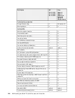
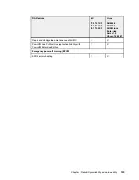
Concurrent maintenance
The IBM POWER8 processor-based systems are designed with the understanding that
certain components have higher intrinsic failure rates than others. These components include
fans, power supplies, and physical storage devices. Other devices, such as I/O adapters, can
become worn from repeated plugging and unplugging. For these reasons, these devices are
concurrently maintainable when properly configured. This feature allows parts to be replaced
while the system is still running, without requiring any downtime to applications. Concurrent
maintenance is facilitated by the redundant design for the power supplies, fans, and physical
storage.
Содержание E850C
Страница 2: ......
Страница 36: ...22 IBM Power System E850C Technical Overview and Introduction...
Страница 114: ...100 IBM Power System E850C Technical Overview and Introduction...
Страница 154: ...140 IBM Power System E850C Technical Overview and Introduction...
Страница 158: ...144 IBM Power System E850C Technical Overview and Introduction...
Страница 159: ......
Страница 160: ...ibm com redbooks Printed in U S A Back cover ISBN 0738455687 REDP 5412 00...

