background image

9.5  Data Register

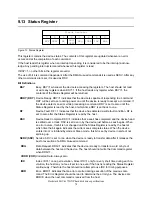
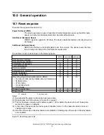
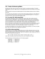
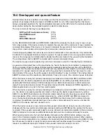
This register is used to transfer data blocks between the device data buffer and the host. It is also the
register through which sector information is transferred on a Format Track command and configuration
information is transferred on an Identify Device command.

All data transfers are 16 bits wide, except for ECC byte transfers, which are 8 bits wide. Data transfers
are PIO only.

The register contains valid data only when DRQ=1 in the Status Register.

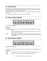
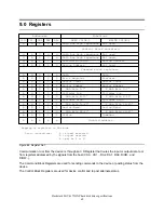
9.6  Device Control Register

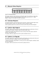
0

–IEN

SRST

1

0

1

2

3

4

5

6

7

Device Control Register

Figure 68. Device Control Register

Bit Definitions

SRST (RST)  Software Reset. The device is held reset when RST=1. Setting RST=0 re-enables the

device.

The host must set RST=1 and wait for at least 5us before setting RST=0 to ensure that
the device recognizes the reset.

-IEN 

Interrupt Enable.  When -IEN=0 and the device is selected, device interrupts to the host
will be enabled. When -IEN=1 or the device is not selected, device interrupts to the host
will be disabled.

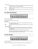
9.7  Drive Address Register

–DS0

–DS1

–H0

–H1

–H2

–H3

–WTG

HIZ

0

1

2

3

4

5

6

7

Drive Address Register

Figure 69. Drive Address Register

This register contains the inverted drive select and head select addresses of the currently selected drive.

Bit Definitions

HIZ 

High Impedance. This bit is not driven and will always be in a high impedance state.

-WTG 

-Write Gate. This bit is 0 when writing to the disk device is in progress.

Deskstar 40GV & 75GXP hard disk drive specifications

71

Содержание DTLA-305040 - Deskstar 41.1 GB Hard Drive

Страница 1: ...XP 3 5 inch Ultra ATA 100 hard disk drive DTLA 307015 DTLA 307020 DTLA 307030 DTLA 307045 DTLA 307060 DTLA 307075 DTLA 305010 DTLA 305020 DTLA 305030 DTLA 305040 Models Revision 2 0 S07 4778 04 IBM st...

Страница 2: ...ay make improve ments and or changes in the product s and or the program s described in this publication at any time It is possible that this publication may contain reference to or information about...

Страница 3: ...agging strategy 17 4 4 7 Operating modes 16 4 4 6 Throughput 15 4 4 5 Buffering Operation Look ahead Write cache 15 4 4 4 Data transfer speed 14 4 4 3 Drive ready time 12 4 4 2 Mechanical positioning...

Страница 4: ...ion labels 61 7 9 Acoustics 60 7 8 5 Rotational shock 59 7 8 4 Nonoperating shock 59 7 8 3 Operating shock 58 7 8 2 Nonoperating vibration 58 7 8 1 Operating vibration 58 7 8 Vibration and shock 57 7...

Страница 5: ...ea Function 87 10 7 5 Command table 84 10 7 4 Operation example 83 10 7 3 Passwords 83 10 7 2 Security level 83 10 7 1 Security mode 83 10 7 Security Mode Feature Set 82 10 6 8 Self test 82 10 6 7 Err...

Страница 6: ...reeze Lock Feature 04h 161 12 29 3 Set Max Unlock Feature 03h 160 12 29 2 Set Max Lock Feature 02h 159 12 29 1 Set Max Set Password Feature 01h 157 12 29 Set Max Address F9h 156 12 28 4 Automatic Acou...

Страница 7: ...193 13 0 Timings 191 12 40 Write Sectors 30h 31h 189 12 39 Write Multiple C5h 187 12 38 Write Long 32h 33h 185 12 37 Write DMA Queued CCh 183 12 36 Write DMA CAh CBh 182 12 35 Write Buffer E8h 181 12...

Страница 8: ...This page intentionally left blank...

Страница 9: ...Ultra DMA cycle timing chart Host terminating Read 33 Figure 29 Ultra DMA cycle timings Host pausing Read 33 Figure 28 Ultra DMA cycle timing chart Host pausing Read 32 Figure 27 Ultra DMA cycle timin...

Страница 10: ...Register Values 75 Figure 73 Reset Response Table 74 Figure 72 Status Register 72 Figure 71 Error Register 72 Figure 70 Device Head Register 71 Figure 69 Drive Address Register 71 Figure 68 Device Co...

Страница 11: ...Max Address F9h 154 Figure 118 Set Features Command EFh 153 Figure 117 Service Command A2h 152 Figure 116 Seek Command 7xh 151 Figure 115 Security Unlock Information 150 Figure 114 Security Unlock Co...

Страница 12: ...Figure 148 Command coverage 2 of 2 195 Figure 148 Command coverage 1 of 2 193 Figure 147 Time out values 191 Figure 146 Write Sectors Command 30h 31h 189 Figure 145 Write Multiple Command C5h Desksta...

Страница 13: ...A 307060 61 4 GB 7200 RPM DTLA 307075 76 8 GB 7200 RPM Note The specifications in this document are subject to change without notice 1 1 Glossary ESD Electrostatic Discharge Kbpi 1 000 bits per inch K...

Страница 14: ...trostatic Discharge Any damage sustained by the drive after removal from the shipping package and opening the ESD protective bag are the responsibility of the user 1 3 References ATA ATAPI 5 T13 1321D...

Страница 15: ...Ring buffer implementation Write Cache Queued feature support Advanced ECC On The Fly EOF Automatic Error Recovery procedures for read and write commands Self Diagnostics on Power on and resident dia...

Страница 16: ...This page intentionally left blank...

Страница 17: ...Part 1 Functional specification Deskstar 40GV 75GXP hard disk drive specifications 5...

Страница 18: ...This page intentionally left blank...
Страница 19: ...an error occurs Monitors various timers such as head settle and servo failure Performs self checkout diagnostics 3 2 Head disk assembly The head disk assembly HDA is assembled in a clean room environ...

Страница 20: ...This page intentionally left blank...
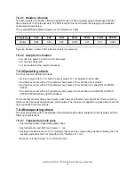
Страница 21: ...15 16 383 20 5 DTLA 307020 15 361 597 440 30 003 120 63 16 15 16 383 15 6 DTLA 307015 41 174 136 880 80 418 240 63 16 15 16 383 41 1 DTLA 305040 30 738 677 760 60 036 480 63 16 15 16 383 30 7 DTLA 305...

Страница 22: ...512 2 048 Data buffer size1 KB 16 6 PIO Mode 4 100 Ultra DMA Mode 5 16 6 PIO Mode 4 100 Ultra DMA Mode 5 Interface transfer rate MB sec 372 max 444 max Media transfer rate Mb sec DTLA 305xxx DTLA 307x...

Страница 23: ...X DTLA 305XXX Figure 3 Cylinder allocation Physical cylinder is calculated from the starting data track of 0 It is not relevant to logical CHS Depend ing on the capacity some of the inner zone cylinde...

Страница 24: ...s Time Typical ms Command type Drive is in quiescent state Figure 4 Command overhead 4 4 2 Mechanical positioning 4 4 2 1 Average seek time without command overhead including settling 10 2 11 2 9 2 10...

Страница 25: ...seek without command overhead including settling 18 7 21 3 15 7 18 3 Write 17 7 19 7 14 7 16 7 Read DTLA 307XXX DTLA 305XXX DTLA 307XXX DTLA 305XXX Max ms Typical ms Function Figure 6 Full stroke seek...

Страница 26: ...rack seek is measured as the average of one 1 single track seek from every track with a random head switch in both directions inward and outward 4 4 2 6 Average latency 4 17 8 3 DTLA 307XXX 5 56 11 1...

Страница 27: ...tion This gives a local average data transfer rate It is derived by the formula Sustained Transfer Rate A B C D where A Number of data sectors per cylinder 512 B of Surface per cylinder 1 Head switch...

Страница 28: ...than sustained data rate T A B C 16 777 216 D 512 E READ where T Calculated time sec A Command process time Command overhead sec B Average seek time sec C Average latency sec D Sustained disk buffer t...

Страница 29: ...r hard reset can change the mode to standby Note Upon power down or spindle stop a head locking mechanism will secure the heads in the OD parking position 4 4 7 2 Mode transition times Mode transition...

Страница 30: ...This page intentionally left blank...
Страница 31: ...orbed by spare tracks of inner zone N N 1 N 2 N 3 defect defect skip skip Figure 16 PList physical format Defects are skipped without any constraint such as track or cylinder boundary The calculation...

Страница 32: ...This page intentionally left blank...

Страница 33: ...re it is possible for data to be lost due to a power off after write command completion There are two ways to check if all data in the write cache has been flushed onto the disk Checking just before p...

Страница 34: ...This page intentionally left blank...

Страница 35: ...424 0 using AMP pins part 350078 4 strip or part 61173 4 loose piece or their equivalents Pin assignments are shown in the figure below 4 3 2 1 Pin Voltage 1 12 V 2 GND 3 GND 4 5V Figure 17 Power conn...

Страница 36: ...of signals Notes 1 O designates an output from the drive 2 I designates an input to the drive 3 I O designates an input output common 4 OC designates open collector or open drain output 5 The signal...

Страница 37: ...ve is prepared to send or receive a 16 bit wide data word This signal is an Open drain output with 24 mA sink capability and an external resistor is needed to pull this line to 5 volts DASP This is a...

Страница 38: ...he resistor value is 50 to 100 DMARQ This signal used for DMA data transfers between host and drive shall be asserted by the drive when it is ready to transfer data to or from the host The direction o...

Страница 39: ...the rising and falling edge of DSTROBE latch the data from DD 15 0 into the host The device may stop toggling DSTROBE to pause an Ultra DMA data in transfer The termination resistors at the device si...

Страница 40: ...reset timing t10 t14 RESET BUSY Figure 20 System reset timing chart 31 RESET high to not BUSY t14 25 RESET low width t10 Max sec Min usec PARAMETER DESCRIPTION Figure 21 System reset timing Deskstar...

Страница 41: ...w t10 10 DIOR DIOW high to CS0 CS1 DA0 2 hold t9 30 CS0 CS1 DA0 02 invalid to IOCS16 negation t8 40 CS0 CS1 DA0 02 valid to IOCS16 assertion t7 5 DIOR high to DD0 15 hold t6 20 DD0 15 setup to DIOR hi...

Страница 42: ...ultiple operations the interval from the end of negation of the DRQ bit until setting of the next DRQ bit is as follows In the event that a host reads the status register only before the sector or blo...

Страница 43: ...te tZ 10 CS 1 0 hold tN 25 CS 1 0 valid to DIOR DIOW tM 35 DIOR DIOW to DMARQ delay tL 25 DIOR DIOW negated pulse width tK 5 DIOR DIOW to DMACK delay tJ 0 DMACK to DIOR DIOW setup tI 10 DIOW data hold...

Страница 44: ...70 Data setup time at device side tDVS 0 0 0 0 0 0 Output enable time tZAD 10 10 10 10 10 10 Output release time tAZ 38 57 86 115 153 230 2 cycle time t2CYC 16 8 25 39 54 73 112 Cycle time tCYC 90 12...

Страница 45: ...to ready response time tSR MAX MIN MAX MIN MAX MIN MAX MIN MAX MIN MAX MIN MODE5 MODE4 MODE3 MODE2 MODE1 MODE0 PARAMETER DESCRIPTION all values in ns Note When a host does not meet tSR it should be re...

Страница 46: ...5 Data hold time at device side tDH 4 0 5 7 7 10 15 Data setup time at device side tDS 20 20 20 20 20 20 Interlocking time tMLI 20 20 20 20 20 20 Output enable time tZAH 10 10 10 10 10 10 Output relea...

Страница 47: ...ACK 4 6 5 5 5 5 5 Data hold time at device side tDH 4 0 5 7 7 10 15 Data setup time at device side tDS 20 20 20 20 20 20 Interlocking time tMLI 20 20 20 20 20 20 Output enable time tZAH 10 10 10 10 10...

Страница 48: ...7 86 115 153 230 2 Cycle time t2CYC 16 8 25 39 54 73 112 Cycle time tCYC 75 0 100 0 100 0 150 0 150 0 150 0 Limited interlock time tLI 0 0 0 0 0 0 Wait time before driving DSTROBE tZIORDY 50 20 55 20...

Страница 49: ...S 20 30 50 Strobe to ready response time tSR MAX MIN MAX MIN MAX MIN MAX MIN MAX MIN MAX MIN MODE5 MODE4 MODE3 MODE2 MODE1 MODE0 PARAMETER DESCRIPTION all values in ns Note When a device does not meet...

Страница 50: ...DMACK negation tACK 4 6 5 5 5 5 5 Data hold time at device side tDH 4 0 5 7 7 10 15 Data setup time at device side tDS 20 20 20 20 20 20 Interlocking time tMLI 75 0 100 0 100 0 150 0 150 0 150 0 Limi...

Страница 51: ...20 Hold time after DMACK negation tACK 4 6 5 5 5 5 5 Data hold time at device side tDH 4 0 5 7 7 10 15 Data setup time at device side tDS 20 20 20 20 20 20 Interlock time tMLI 75 0 100 0 100 0 150 0...

Страница 52: ...Reg Sector number Reg 1 1 0 1 0 Sector count Reg Sector count Reg 0 1 0 1 0 Features Reg Error Reg 1 0 0 1 0 Data Reg Data Reg 0 0 0 1 0 Command Block Registers DIOW 0 Write DIOR 0 Read DA0 DA1 DA2 CS...

Страница 53: ...r Device 1 Cable Selection and Device 0 Forcing Device 1 Present is shown below The Device 0 setting automatically recognizes device 1 if present The Device 0 Forcing Device 1 present setting is for a...

Страница 54: ...o enable the CSEL mode Cable Selection mode the jumper block must be installed at E F In the CSEL mode the drive address is determined by AT interface signal 28 CSEL as follows When CSEL is grounded o...

Страница 55: ...Figure 45 Jumper positions for 15 logical head default Notes 1 To enable the CSEL mode Cable Selection mode the jumper block must be installed at E F In the CSEL mode the drive address is determined...

Страница 56: ...ogical heads The above jumper setting forces the values of Word 1 3 6 and 60 61 in Identify Device data as follows DTLA 305040 307045 307060 307075 Word 1 3 6 C H S Remain ship default value Word 60 6...

Страница 57: ...tings are used for limiting power supply current when multiple drives are used 2 Command to spin up is SET FEATURES subcommand 07h Refer to 12 28 Set Features 3 To enable the CSEL mode Cable Selection...

Страница 58: ...15 C Hour 300 to 3 048 m Temperature Relative humidity Maximum wet bulb temperature Maximum temperature gradient Altitude Operating conditions Figure 48 Operating and nonoperating conditions Notes 1 T...

Страница 59: ...40 50 60 70 80 90 100 Relative Humidity Environment Specification Wet Bulb 29 4C Wet Bulb 35C 36C 95 31C 90 55C 15 65C 14 Nonoperating Operating Figure 49 Limits of temperature and humidity Deskstar 4...

Страница 60: ...n up Input voltage Figure 50 Input voltage Note To avoid damage to the drive electronics power supply voltage spikes must not exceed specifi cations 7 5 2 Power supply current typical DTLA 305010 3050...

Страница 61: ...26 Standby average 11 5 0 78 0 41 Random R W average2 2 23 1 02 Random R W peak 1 81 0 81 Start up max 11 4 0 84 0 27 Seek average1 2 23 0 47 Seek peak 0 63 0 32 Idle ripple peak to peak 8 1 0 57 0 2...

Страница 62: ...n tolerance A common supply with separate power leads to each drive is a more desirable method of power distribution To prevent external electrical noise from interfering with the performance of the d...

Страница 63: ...Figure 54 Typical Current Form of 12V at Start Up of DTLA 307015 307020 307030 307045 7 5 4 3 DTLA 307060 307075 Figure 55 Typical Current Form of 12V at Start Up of DTLA 307060 307075 Deskstar 40GV...

Страница 64: ...307020 0 43 307015 0 12 305040 0 16 305030 0 24 305020 Energy consumption efficiency W GB DTLA Figure 56 Energy consumption efficiency Energy consumption efficiency is calculated as Power consumption...

Страница 65: ...Start stop cycles The drive withstands a minimum of 40 000 start stop cycles in a 40 C environment and a minimum of 10 000 start stop cycles in extreme temperature or humidity or complete stop disk ro...

Страница 66: ...tions 7 7 1 Outline 25 4 0 4 101 6 0 4 146 0 6 BREATHER HOLE LEFT FRONT DO NOT BLOCK THE BREATHER HOLE 38 9 0 4 19 7 0 4 Dia 2 0 0 1 Figure 57 Outline of the DTLA 3xxxxx Deskstar 40GV 75GXP hard disk...

Страница 67: ...TLA 307xxx hard disk drive form factor 670 307060 307075 590 307015 307020 307030 307045 550 146 0 0 8 101 6 0 4 25 4 0 4 305010 305020 305030 305040 Weight grams Length mm Width mm Height mm DTLA Fig...

Страница 68: ...lowable penetration of noted screw to be 4 5 mm Max allowable penetration of noted screw to be 4 0 mm Recommended torque 0 6 1 0 Nm REAR RIGHT 6X 6 35 0 2 2X 95 25 0 2 6X 6 32 UNC 4X 6 32 UNC 2X 44 45...

Страница 69: ...d mounting screw torque is 0 6 1 0 Nm 6 10 Kgf cm The recommended mounting screw depth is 4 mm maximum for bottom and 4 5 mm maximum for hori zontal mounting If an electrical screw driver is used for...

Страница 70: ...02 Horizontal x10 3 G2 Hz RMS G 500 Hz 200 Hz 150 Hz 65 Hz 62 Hz 48 Hz 45 Hz 17 Hz 5 Hz Direction Figure 61 Random vibration PSD profile break points operating The overall RMS root mean square level...

Страница 71: ...on in all models No data loss occurs with a 55 G half sine shock pulse of 2 ms duration in models DTLA 307060 307075 No data loss occurs with a 65 G half sine shock pulse of 2 ms duration in models DT...

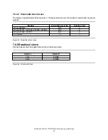
Страница 72: ...25 DTLA 307060 307075 2 350 DTLA 307015 307020 307030 307045 2 400 DTLA 305XXX Duration ms Accleration level G Models Figure 63 Sinusoidal shock wave 7 8 5 Rotational shock All shock inputs shall be a...

Страница 73: ...DTLA 305010 305020 305030 305040 Mode Figure 65 Sound power levels Mode definition Idle mode The drive is powered on disks spinning track following unit ready to receive and re spond to interface com...

Страница 74: ...UL recognition or the CSA certification is maintained for the product life The UL and C UL recognition mark or the CSA monogram for CSA certification appear on the drive 7 11 2 IEC compliance The prod...

Страница 75: ...SD environment Radiated Electromagnetic Susceptibility RES Spectrum Management Agency SMA EMC requirements of Australia The SMA has approved two forms of C Tick Marking for IBM 7 13 CE Mark The produc...

Страница 76: ...This page intentionally left blank...
Страница 77: ...Part 2 Interface specification Deskstar 40GV 75GXP hard disk drive specifications 65...

Страница 78: ...This page intentionally left blank...

Страница 79: ...to which the device is attached Host The DTLA 30XXXX hard disk drive Device 8 2 Deviations from standard The device conforms to the referenced specifications with the following deviations Check Power...

Страница 80: ...This page intentionally left blank...

Страница 81: ...used Data bus high impedance x 0 1 A N Not used Data bus high impedance x x 0 A N Control block registers Not used Data bus high impedance x x x N N WRITE DIOW READ DIOR DA0 DA1 DA2 CS1 CS0 Functions...

Страница 82: ...ister 9 3 Cylinder High Register This register contains the high order bits of the starting cylinder address for any disk access At the end of the command this register is updated to reflect the curre...

Страница 83: ...held reset when RST 1 Setting RST 0 re enables the device The host must set RST 1 and wait for at least 5us before setting RST 0 to ensure that the device recognizes the reset IEN Interrupt Enable Wh...

Страница 84: ...is by CHS mode When L 1 addressing is by LBA mode DRV Device When DRV 0 device 0 master is selected When DRV 1 device 1 slave is selected HS3 HS2 HS1 HS0 Head Select These four bits indicate binary e...

Страница 85: ...r has occurred on the data bus during Ultra DMA transfer ICRCE CRC 9 10 Features Register This register is command specific This is used with the Set Features command and S M A R T Function Set comman...

Страница 86: ...detected a write fault condition DF is set to zero after the Status Register is read by the host DSC Device Seek Complete DSC 1 indicates that a seek has completed and the device head is settled over...

Страница 87: ...S set by Initialize Device Parameters Multiple mode Write Cache Read look ahead ECC bytes O O O PDIAG handshake X O O DASP handshake O O O Initialization of registers 2 X X O Spinning spindle X X O In...

Страница 88: ...Figure 74 Default Register Values After power on hard reset or software reset the register values are initialized as shown in the figure below Device 1 failed 8xh Controller microprocessor error 05h E...

Страница 89: ...Device 1 if it is present in order to indicate device active Execute Device Diagnostic If Device 1 is present Device 0 shall read PDIAG to determine when it is valid to clear the BSY bit and if Devic...

Страница 90: ...anslation mode but cannot exceed 65535 0FFFFh When the host selects a CHS translation mode using the INITIALIZE DEVICE PARAMETERS command the host requests the number of sectors per logical track and...

Страница 91: ...and and the results are indeterminate If any error occurs the command queue is aborted When the device is ready to continue processing a bus released command and BSY and DRQ are both cleared to zero t...

Страница 92: ...ode command enables a host to determine if a device is currently in going into or leaving standby mode The Idle and Idle Immediate commands move a device to idle mode directly from the active or stand...

Страница 93: ...prediction of degrading or faulty conditions for that particular device The specific set of attributes being used and the identity of these attributes is vendor specific and proprietary 10 6 2 Attrib...

Страница 94: ...ors that the device reported as described in the SMART error log sector The device may also provide additional vendor specific information on these reported errors The error log is not disabled when S...

Страница 95: ...ity Freeze Lock command It cannot quit this mode until power off 10 7 2 Security level The following security levels are provided High level security When the device lock function is enabled and the U...

Страница 96: ...rd command without enabling the Device Lock Function The Master Password Revision Code is set to FFFEh as shipping default by the drive manufacturer 10 7 4 2 User Password setting When a User Password...

Страница 97: ...1 Password Erase Unit Password Match Reject Complete Complete Erase Unit Lock function Disable Normal operation All commands are available Freeze Lock command Enter Device Frozen mode Normal Operation...

Страница 98: ...d Normal operation but data lost Figure 80 Password Lost 10 7 4 5 Attempt limit for SECURITY UNLOCK command The SECURITY UNLOCK command has an attempt limit The purpose of this attempt limit is to pre...

Страница 99: ...Unit Executable Executable Executable Security Erase Prepare Command aborted Executable Command aborted Security Disable Password Executable Executable Executable Recalibrate Executable Executable Com...

Страница 100: ...xecutable Executable Command aborted Write Long w o retry Executable Executable Command aborted Write DMA Queued Executable Executable Command aborted Write DMA w retry Executable Executable Command a...

Страница 101: ...4GB besides flagged media defects not visible by system 2 Preparation of drives by the system manufacturer Special utility software is required to define the size of the protected area and to store th...

Страница 102: ...during the cur rent power on cycle The password does not persist over a power cycle but does persist over a hardware or software reset This password is not related to the password used for the Securi...

Страница 103: ...h overlap Host process Device process Seek operation Overhead Total time n 1 Seek operation A B Figure 82 Seek overlap 10 10 Write cache function Write cache is a performance enhancement whereby the d...

Страница 104: ...ned ERP is fully carried out a hard error is reported to the host system This location is registered internally as a candidate for the reallocation When a registered location is specified as a target...

Страница 105: ...bled and the associated algorithm indicates that the Standby mode should be entered to reduce acoustical emanations The IDENTIFY DEVICE response word 83 bit 3 indicates that Advanced Power Management...

Страница 106: ...ser area can be accessed But any com mands which access sectors across the original native maximum LBA are rejected with error even if this protection is removed by an Set Max Address command 10 15 1...

Страница 107: ...essible System reserved area LBA 0 LBA M R LBA M Figure 83 Device address map before and after Set Feature 10 15 2 Identify Device Data Identify Device data word 83 bit 7 indicates the device supports...

Страница 108: ...This page intentionally left blank...

Страница 109: ...as a device that is no longer responding Interrupts are cleared when the host reads the Status Register issues a reset or writes to the Command Register Figure 147 on page 0 shows the device time out...

Страница 110: ...rt the command by setting BSY 0 ERR 1 ABT 1 and interrupting the host If an error occurs the device will set BSY 0 ERR 1 and DRQ 1 The device will then store the error status in the Error Register and...

Страница 111: ...sector or block b The host writes one sector or block of data via the Data Register c The device sets BSY 1 after it has received the sector or block d When the device has finished processing the sect...

Страница 112: ...rs the device will set BSY 0 and ERR 1 store the error status in the Error Register and interrupt the host The registers will contain the location of the sector in error The errored location will be r...

Страница 113: ...ion SMART Return Status SMART Save Attribute Values SMART Enable Disable Automatic Off Line Data Collection Standby Standby Immediate Execution of these commands involves no data transfer 1 The host w...

Страница 114: ...he DMA channel prior to reading status from the device The DMA protocol allows high performance multitasking operating systems to eliminate processor over head associated with PIO transfers 1 Host ini...

Страница 115: ...ready for data transfer REL is cleared a the host transfers the data for the command identified by the Tag number using the DMA transfer protocol currently in effect b the device generates an interrup...

Страница 116: ...This page intentionally left blank...
Страница 117: ...0 1 0 0 0 0 1 21 Read Sectors no retry 1 0 0 1 0 0 0 0 0 20 Read Sectors retry 1 1 1 1 1 1 0 0 0 F8 Read Native Max Address 3 1 1 0 0 0 1 0 0 C4 Read Multiple 1 0 0 1 0 0 0 1 1 23 Read Long no retry 1...

Страница 118: ...0 0 B0 SMART Enable Disable Automatic Off line Data Collection 3 1 0 1 1 0 0 0 0 B0 SMART Write Log Sector 2 1 0 1 1 0 0 0 0 B0 SMART Read Log Sector 1 1 0 1 1 0 0 0 0 B0 SMART Save Attribute Values...

Страница 119: ...Disable Automatic Off line Feature Register Hex Command Code Hex Command Subcommand Figure 85 Command set Subcommand Figure 84 on pages 30 and 0 shows the commands that are supported by the device Fi...

Страница 120: ...o zero 1 Indicates that the bit is always set to one H Head number Indicates that the head number part of the Device Head Register is an input parameter and will be set by the device V Valid Indicates...

Страница 121: ...0 0 0 ERR IDX COR DRQ DSC DF RDY BSY AMN T0N ABT 0 IDN 0 UNC CRC 0 1 2 3 4 5 6 7 0 1 2 3 4 5 6 7 Status Register Error Register Figure 86 Check Power Mode Command E5h 98h The Check Power Mode command...

Страница 122: ...0 V V V V V V V V ERR IDX COR DRQ DSC DF RDY BSY AMN T0N ABT 0 IDN 0 UNC CRC 0 1 2 3 4 5 6 7 0 1 2 3 4 5 6 7 Status Register Error Register Figure 87 Execute Device Diagnostic Command 90h The Execute...

Страница 123: ...5 4 3 2 1 0 Register Command Block Input Registers Command Block Output Registers V 0 V 0 V 0 0 0 V 0 0 0 0 0 ERR IDX COR DRQ DSC DF RDY BSY AMN T0N ABT 0 IDN 0 UNC CRC 0 1 2 3 4 5 6 7 0 1 2 3 4 5 6...

Страница 124: ...not verified with read operation whether the sector of data is initialized correctly Any data previously stored on the track will be lost The host may transfer a sector of data containing a format ta...

Страница 125: ...er specifies current LBA address bits 8 15 Low 16 23 High H In LBA mode this register specifies current LBA address bits 24 27 L 1 Error The Error Register An Abort error ABT 1 will be returned when L...

Страница 126: ...ter command completion of this command and are used at next power on reset or hard reset Previous information of reassign and defect are erased from the device by executing this command Note that the...

Страница 127: ...or Count see below Error Feature Data Data 7 6 5 4 3 2 1 0 Register 7 6 5 4 3 2 1 0 Register Command Block Input Registers Command Block Output Registers V 0 0 V 0 0 0 V 0 0 0 0 0 ERR IDX COR DRQ DSC...

Страница 128: ...ique length selected via set feature cmd 0028H 22 Buffer size in 512 byte increments XXXXH 21 Controller type 0003 dual ported multiple sector buffer with look ahead read 0003H 20 Serial number in ASC...

Страница 129: ...umber of User Addressable Sectors Word 60 specifies the low word of the number xxxxH 60 61 Current Multiple setting Bit assignments 15 9 0 Reserved 8 1 Multiple Sector Setting is Valid 7 0 xxh Current...

Страница 130: ...and set supported 15 0 Reserved 14 1 NOP command 13 1 READ BUFFER command 12 1 WRITE BUFFER command 11 0 Reserved 10 1 Host Protected Area feature set 9 0 DEVICE RESET command 8 0 SERVICE interrupt 7...

Страница 131: ...ecurity extensions enabled 7 Set Features Address Offset mode 6 Set Features subcommand required to spin up after power up 5 Power Up In Standby feature set enabled 4 Removable Media Status Notificati...

Страница 132: ...n 1 assert 0 not assert 10 9 How to determine the device number 00 Reserved 01 Jumper 10 CSEL signal 11 Some other method 8 Shall be set to one if Dev 1 7 0 Dev 0 H W reset result 7 Reserved 6 Respond...

Страница 133: ...ved 0000H 160 254 Reserved xxxxH 130 159 Current Set Feature Option Bit assignments 15 4 Reserve 3 Auto reassign 1 Enable 2 Reverting 1 Enable 1 Read Look ahead 1 Enable 0 Write Cache 1 Enable xxxxH 1...

Страница 134: ...e immediately and to set the auto power down time out parameter standby timer And the timer then starts counting down When the Idle mode is entered the device is spun up to operating speed If the devi...

Страница 135: ...enter Standby mode automatically if the time out interval expires with no drive access from the host The time out interval will be reinitialized if there is a drive access before the time out interva...

Страница 136: ...0 0 0 ERR IDX COR DRQ DSC DF RDY BSY AMN T0N ABT 0 IDN 0 UNC CRC 0 1 2 3 4 5 6 7 0 1 2 3 4 5 6 7 Status Register Error Register Figure 94 Idle Immediate Command E1h 95h The Idle Immediate command cau...

Страница 137: ...r of heads minus 1 per cylinder Words 54 58 in Identify Device Information reflect these para meters The parameters remain in effect until following events Another Initialize Device Parameters command...

Страница 138: ...put Registers Command Block Output Registers V 0 0 V 0 0 0 V 0 0 0 0 0 ERR IDX COR DRQ DSC DF RDY BSY AMN T0N ABT 0 IDN 0 UNC CRC 0 1 2 3 4 5 6 7 0 1 2 3 4 5 6 7 Status Register Error Register Figure...

Страница 139: ...C DF RDY BSY AMN T0N ABT 0 IDN 0 UNC CRC 0 1 2 3 4 5 6 7 0 1 2 3 4 5 6 7 Status Register Error Register Figure 97 Read Buffer Command E4h The Read Buffer command transfers a sector of data from the se...

Страница 140: ...nd reads one or more sectors of data from disk media then transfers the data from the device to the host The sectors are transferred through the Data Register 16 bits at a time The host initializes a...

Страница 141: ...ers from the device Sector Count The number of requested sectors not transferred This will be zero unless an unrecoverable error occurs Sector Number The sector number of the last transferred sector L...

Страница 142: ...d Command C7h This command executes in a similar manner to a READ DMA command The device may perform a bus release or it may execute the data transfer without performing a bus release if the data is r...

Страница 143: ...orms a bus release This bit is set to one when the device is ready to transfer data Input parameters from the device on command complete Sector Count bits 7 3 Tag contain the Tag of the completed comm...

Страница 144: ...nd ECC bytes from the device to the host After 512 bytes of data have been transferred the device will keep setting DRQ 1 to indicate that the device is ready to transfer the ECC bytes to the host The...

Страница 145: ...h Low The cylinder number of the transferred sector L 0 In LBA mode this register contains current LBA bits 8 15 Low 16 23 High L 1 H The head number of the transferred sector L 0 In LBA mode this reg...

Страница 146: ...tors of data from disk media then transfers the data from the device to the host The sectors are transferred through the Data Register 16 bits at a time Command execution is identical to the Read Sect...

Страница 147: ...sferred sector L 0 In LBA mode this register contains current LBA bits 0 7 L 1 Cylinder High Low The cylinder number of the last transferred sector L 0 In LBA mode this register contains current LBA b...

Страница 148: ...7 0 1 2 3 4 5 6 7 Status Register Error Register Figure 102 Read Native Max LBA CYL F8h This command returns the native max LBA CYL of the drive which is not effected by Set Max Address command Input...

Страница 149: ...reads one or more sectors of data from disk media then transfers the data from the device to the host The sectors are transferred through the Data Register 16 bits at a time If an uncorrectable error...

Страница 150: ...sferred sector L 0 In LBA mode this register contains current LBA bits 0 7 L 1 Cylinder High Low The cylinder number of the last transferred sector L 0 In LBA mode this register contains current LBA b...

Страница 151: ...s one or more sectors on the device No data is transferred to the host The difference of Read Sectors command and Read Verify Sectors command is whether the data is transferred to the host or not If a...

Страница 152: ...erred sector L 0 In LBA mode this register contains current LBA bits 0 7 L 1 Cylinder High Low The cylinder number of the last transferred sector L 0 In LBA mode this register contains current LBA bit...

Страница 153: ...and Block Input Registers Command Block Output Registers V 0 V 0 V 0 0 V V 0 0 0 0 0 ERR IDX COR DRQ DSC DF RDY BSY AMN T0N ABT 0 IDN 0 UNC CRC 0 1 2 3 4 5 6 7 0 1 2 3 4 5 6 7 Status Register Error Re...

Страница 154: ...unction The Security Disable Password command requests a transfer of a single sector of data from the host including information specified in the figure below Then the device checks the transferred pa...

Страница 155: ...should check the supplied password against the user password stored internally One indicates that the device should check the given password against the master password stored internally Deskstar 40GV...

Страница 156: ...0 0 0 0 0 ERR IDX COR DRQ DSC DF RDY BSY AMN T0N ABT 0 IDN 0 UNC CRC 0 1 2 3 4 5 6 7 0 1 2 3 4 5 6 7 Status Register Error Register Figure 108 Security Erase Prepare Command F3h The Security Erase Pr...

Страница 157: ...ster Error Register Figure 109 Security Erase Unit Command F4h The Security Erase Unit command initializes all user data sectors and then disables the device lock function Note that the Security Erase...

Страница 158: ...Also the defective sector information and the reassigned sector information for the device are not updated The security erase prepare command should be completed immediately prior to the Security Eras...

Страница 159: ...T0N ABT 0 IDN 0 UNC CRC 0 1 2 3 4 5 6 7 0 1 2 3 4 5 6 7 Status Register Error Register Figure 111 Security Freeze Lock Command F5h The Security Freeze Lock Command allows the device to enter frozen mo...

Страница 160: ...ord Command F1h The Security Set Password command enables security mode feature device lock function and sets the master password or the user password The security mode feature device lock function is...

Страница 161: ...vi ce accepts the command with a value of 0000h or FFFFh in this field but does not change the Master Password Revision code The setting of the Identifier and Security level bits interact as follows I...

Страница 162: ...s completed the device will be in device lock mode The password has not been changed yet The Security Unlock command requests to transfer a single sector of data from the host including infor mation s...

Страница 163: ...device regards Password as Master Password The user can detect if the attempt to unlock the device has failed due to a mismatched password as this is the only reason that an abort error will be return...

Страница 164: ...ek command initiates a seek to the designated track and selects the designated head The device need not be formatted for a seek to execute properly Output parameters to the device Sector Number In LBA...

Страница 165: ...A2h The Service command is used to provide data transfer and or status of a command that was previously bus released Output parameters to the device D Selected device Input parameters from the device...

Страница 166: ...EFh The Set Feature command is to establish the following parameters which affect the execution of certain features as shown in below table ABT will be set to 1 in the Error Register if the Feature r...

Страница 167: ...Default Transfer Mode 00000 000 PIO Default Transfer Mode Disable IORDY 00000 001 PIO Flow Control Transfer Mode x 00001 nnn nnn 000 001 010 011 100 Multiword DMA mode x 00100 nnn nnn 000 001 010 Ultr...

Страница 168: ...Power Saving becomes normal Idle 12 28 4 Automatic Acoustic Management When Feature register is 42h Enable Automatic Acoustic Management the Sector Count Register specifies the Automatic Acoustic Mana...

Страница 169: ...Address command the device regards as Set Max security extensions command according to feature register value Valid features values are as shown below 1 01h indicates Set Max Set Password command 2 0...

Страница 170: ...h which is to be set L 1 In CHS mode this register contains cylinder number which is to be set L 0 H In LBA mode this register contains LBA bits 24 27 which is to be set L 1 In CHS mode this register...

Страница 171: ...CRC 0 1 2 3 4 5 6 7 0 1 2 3 4 5 6 7 Status Register Error Register Figure 120 Set Max Set Password The device regards as Set Max Address command if this command is immediately preceded by a Read Nativ...

Страница 172: ...COR DRQ DSC DF RDY BSY AMN T0N ABT 0 IDN 0 UNC CRC 0 1 2 3 4 5 6 7 0 1 2 3 4 5 6 7 Status Register Error Register Figure 122 Set Max Lock The device regards as Set Max Address command if this command...

Страница 173: ...ce regards as Set Max Address command if this command is immediately preceded by a Read Native Max Address command This command requests a transfer of a single sector of data from the host including t...

Страница 174: ...DRQ DSC DF RDY BSY AMN T0N ABT 0 IDN 0 UNC CRC 0 1 2 3 4 5 6 7 0 1 2 3 4 5 6 7 Status Register Error Register Figure 124 Set Max Freeze Lock F9h If the Set Max Freeze Lock command is immediately prece...

Страница 175: ...ister Figure 125 Set Multiple Command C6h The Set Multiple command enables the device to perform Read and Write Multiple commands and estab lishes the block size for these commands The block size is t...

Страница 176: ...k Output Registers V 0 V 0 V 0 0 0 V 0 0 0 0 0 ERR IDX COR DRQ DSC DF RDY BSY AMN T0N ABT 0 IDN 0 UNC CRC 0 1 2 3 4 5 6 7 0 1 2 3 4 5 6 7 Status Register Error Register Figure 126 Sleep Command E6h 99...

Страница 177: ...ands that can be used for logging and reporting purposes and to accommodate special user needs The S M A R T Function Set command has several separate subcommands which are selectable via the Features...

Страница 178: ...the device before issuing the SMART Enable Disable Attribute Autosave subcommand will cause this feature to be enabled Any other non zero value written by the host into this register before issuing th...

Страница 179: ...log sector address Read Write Host vendor specific 80h 9Fh Read Only SMART Self test log 06h Read Only SMART Error Log 01h Type Content Log sector address Figure 128 Log sector addresses 12 32 7 SMART...

Страница 180: ...Exceeded Condition the device loads 4Fh into the Cylinder Low register and C2h into the Cylinder High register If the device detects a Threshold Exceeded Condition the device loads F4h into the Cylin...

Страница 181: ...t failure check point 01h 172h 1 SMART device error logging capability 0003h 170h 2 SMART capability 1Bh 16Fh 1 Off line data collection capability 16Eh 1 Vendor specific 16Ch 2 Total time in seconds...

Страница 182: ...Number indicates an active attribute The device supports the following Attribute ID Numbers Ultra DMA CRC Error Count 199 Off line Scan Uncorrectable Sector Count 198 Current Pending Sector Count 197...

Страница 183: ...tomatic Off line Data Collection is enabled 0 Automatic Off line Data Collection is disabled Bits 0 thru 6 represents a hexadecimal status value reported by the device Value Definition 0 Off line data...

Страница 184: ...implemented bit 1 1 SMART Execute Off line Immediate subcommand is implemented 0 SMART Execute Off line Immediate subcommand is not implemented Execute Off line Immediate implemented bit 0 Definition...

Страница 185: ...ing Attribute Values 512 1FFh 1 Data structure checksum 00h 17Ch 131 Vendor specific 00h 16Ah 18 Reserved 15Eh 12 30th Device Attribute 02h 12 1st Device Attribute 0010h 00h 2 Data Structure Revision...

Страница 186: ...hese data structures are in byte ordering 512 1FFh 1 Data structure checksum 1C6h 57 Reserved 1C4h 2 Device error count 16Ah 90 5th error log data structure 110h 90 4th error log data structure B6h 90...

Страница 187: ...e Description Figure 134 Error log data structure Command data structure Data format of each command data structure is shown below 12 08h 4 Timestamp ms from Power On 07h 1 Command register 06h 1 Devi...

Страница 188: ...Sector number register 02h 1 Sector count register 01h 1 Error register 00h 1 Reserved Offset Byte Description Figure 136 Error data structure The state field contains a value indicating the device st...

Страница 189: ...1 Self test execution status n 18h 02h 1 Self test number 00h 2 Data structure revision Offset Byte Description Figure 137 Self test log data structure The data structure contains the descriptor of S...

Страница 190: ...nd subcommand other than SMART ENABLE OPERATIONS was received by the de vice while the device was in a S M A R T Disabled state 04h 51h A S M A R T FUNCTION SET command was received by the device with...

Страница 191: ...7 Status Register Error Register Figure 139 Standby Command E2h 96h The Standby command causes the device to enter the Standby Mode immediately and to set the auto power down time out parameter stand...

Страница 192: ...10 seconds 254 8 hours 253 21 minutes 252 Value 240 30 minutes 241 251 Value 5 seconds 1 240 Timer disabled 0 Time out Value When the automatic power down sequence is enabled the drive will enter Sta...

Страница 193: ...0N ABT 0 IDN 0 UNC CRC 0 1 2 3 4 5 6 7 0 1 2 3 4 5 6 7 Status Register Error Register Figure 140 Standby Immediate Command E0h 94h The Standby Immediate command causes the device to enter Standby mode...

Страница 194: ...0 0 0 0 0 ERR IDX COR DRQ DSC DF RDY BSY AMN T0N ABT 0 IDN 0 UNC CRC 0 1 2 3 4 5 6 7 0 1 2 3 4 5 6 7 Status Register Error Register Figure 141 Write Buffer Command E8h The Write Buffer command transfe...

Страница 195: ...e The data is then written to the disk media The sectors of data are transferred through the Data Register 16 bits at a time The host initializes a slave DMA channel prior to issuing the command Data...

Страница 196: ...d sectors not transferred This will be zero unless an unrecoverable error occurs Sector Number The sector number of the last transferred sector L 0 In LBA mode this register contains current LBA bits...

Страница 197: ...d Command CCh This command executes in a similar manner to a WRITE DMA command The device may perform a bus release or it may execute the data transfer without performing a bus release if the data is...

Страница 198: ...performs a bus release This bit is set to 1 when the device is ready to transfer data Input parameters from the device on Command Complete Sector Count bits 7 3 Tag contain the Tag of the completed c...

Страница 199: ...written to the disk media After 512 bytes of data have been transferred the device will keep setting DRQ 1 to indicate that the device is ready to receive the ECC bytes from the host The data is tran...

Страница 200: ...Low 16 23 High L 1 H The head number of the sector to be transferred L 0 In LBA mode this register contains current LBA bits 24 27 L 1 The drive internally uses 40 bytes of ECC on all data read or wri...

Страница 201: ...more sectors from the host to the device the data is written to the disk media Command execution is identical to the Write Sectors command except that an interrupt is generated for each block as defin...

Страница 202: ...erred sector L 0 In LBA mode this register contains current 1 5 LBA bits 0 7 L 1 Cylinder High Low The cylinder number of the last transferred sector L 0 In LBA mode this register contains current LBA...

Страница 203: ...t to the device the data is then written to the disk media The sectors are transferred through the Data Register 16 bits at a time If an uncorrectable error occurs the write will be terminated at the...

Страница 204: ...sferred sector L 0 In LBA mode this register contains current LBA bits 0 7 L 1 Cylinder High Low The cylinder number of the last transferred sector L 0 In LBA mode this register contains current LBA b...

Страница 205: ...pt DRQ For Data Transfer In 400 ns Status Register BSY 1 OUT To Command Register Device Busy After Command Code Out Data In Command 31 sec Status Register BSY 0 and RDY 1 Bus RESET Signal Asserted Dev...

Страница 206: ...This page intentionally left blank...

Страница 207: ...EVICE PARAMETERS 91h Mandatory Yes EXECUTE DEVICE DIAGNOSTIC 90h Optional No CFA TRANSLATE SECTORS 87h Mandatory Yes SEEK 7xh Obsoleted Yes FORMAT TRACK 50h Obsoleted Yes READ VERIFY SECTORS S w o ret...

Страница 208: ...SLEEP E6h Mandatory Yes CHECK POWER MODE E5h Optional Yes READ BUFFER E4h Mandatory Yes IDLE E3h Mandatory Yes STANDBY E2h Mandatory Yes IDLE IMMEDIATE E1h Mandatory Yes STANDBY IMMEDIATE E0h Optiona...

Страница 209: ...look ahead feature AAh No Enable Media Status Notification 95h Yes Disable Address Offset mode 89h Yes Disable Power up in Standby mode 86h Yes Disable Advanced Power Management 85h Yes Disable write...

Страница 210: ...This page intentionally left blank...
Страница 211: ...eviations from standard 67 Dimensions 55 DMA commands 102 DMA queued commands 103 DMA timings 31 Drive ready time 14 DRQ interval time 30 E ECC On The Fly correction 53 Electrical interface 23 Electro...

Страница 212: ...sign Function 92 Registers 69 Reliability 53 Reset 75 Reset timings 28 S S M A R T 81 Safety 62 Sector Addressing Mode 78 Security 83 Seek Overlap 91 SET FEATURES Command Support Coverage 197 Shipped...

Отзывы: